Difference between revisions of "Dallas DS18b20"
Grovkillen (talk | contribs) |
|||
| Line 1: | Line 1: | ||
= Introduction = | = Introduction = | ||
| − | |||
| − | + | [[File:DS18B20 Pure Breakout2.jpg|400px]] | |
| − | + | [[File:DS18B20.jpg|300px]] | |
| − | |||
| − | + | The DS18B20 manufactured by Dallas and Maxxim is a very simple to use temperature sensor | |
| − | + | with a tolerance of +/- 0.5°C. (Remember: Cheap remakes from chinese market might have bigger tolerance.) | |
| − | + | It's advantages: | |
| − | + | Very simple to use due to "One Wire" data protocol. | |
| − | + | Chainable, it is possible to chain up to 100 sensors on one cable (remember ESPEasy has 12 tasks max...). | |
| − | + | No calibration necessary if the tolerance fits your needs as the sensor gives digital data directly. | |
| − | + | Many forms availlable from bare chip to waterproof and tube sensors. | |
| − | |||
| − | |||
| − | |||
| − | + | [[File:DS18B20 cabled.jpg|400px]] | |
| − | |||
| − | + | Every DS18B20 has a unique adress burned in at production time. | |
| + | This UID (Unique IDentifier) is used to tell the sensors apart on one single cable. | ||
| − | + | = Precautions = | |
| − | + | The DS18B20 runs well on 3,3V so no level shifter or special power supply is needed. | |
| − | + | The sensor needs a pull up resistor. If you use the breakout board type the resistor usually | |
| + | is already on the board. This gets you into problems if using several DS18B20 breakout boards- | ||
| + | As there should be only one resistor on the whole line you might have to remove | ||
| + | resistors leaving just one at one end of the line. | ||
| − | + | Cabling: | |
| + | Do not use very thin cabling! | ||
| + | Tested with a 3*0,14mm² cable the length with 5 Sensors was 10 meters, longer cabling did not work. | ||
| + | Use a phone cable (2*2*0.6mm²) instead if you need long distances up to 50..100 meters. | ||
| + | remember: One (!) pull-up resistor for the whole line! | ||
| + | The preferred structure is a straight line. If possible avoid "stubs". | ||
| + | If necessary it can be cabled in a "star" infrastructure. | ||
| + | But be aware that stubs and star form reduce the possible cable length. | ||
| − | + | = Hardware = | |
| − | + | Connecting the DS18B20 is done easily. | |
| + | Just connect it as shown in the schematic: | ||
| − | [[File: | + | [[File:DS18B20-Schematic.jpg|500px]] |
| − | == ESP | + | As you can see the sensors are just lined up, no aditional "trick work" necessary. |
| − | + | Testing was made with a simple breadboard circuit: | |
| + | |||
| + | [[File:DS18B20 Breadboard-Example.jpg|500px]] | ||
| + | |||
| + | = ESPEasy = | ||
| + | |||
| + | Chose a task to set up the DS18B20. | ||
| + | |||
| + | [[File:DS18B20-Setup Step 1.jpg|500px]] | ||
| + | |||
| + | There is no device address at this time, they will show up later. | ||
| + | Set the GPIO field to the GPIO you connected the sensor(s) to. | ||
| + | |||
| + | ==Additional setting== | ||
| + | Device resolution: | ||
| + | The device resolution can be set. The lower the resolution the accuracy decreases and the speed increases. | ||
| + | As temperatures do not change very fast usually a high accuracy can be choosen without problem. | ||
| + | |||
| + | Submit the settings to the ESP. | ||
| + | |||
| + | Now the Device address field shoud get alive. | ||
| + | |||
| + | [[File:DS18B20-Setup Step 2.jpg|500px]] | ||
| + | |||
| + | If you have only one DS18B20 connected just chose the single address shown and submit. | ||
| + | If you have several DS18B20 it's a good idea to connect one by one and note the addresses before installing | ||
| + | all in a line - it gets confusing otherwise. | ||
| + | |||
| + | Remeber you have to setup a task for every single sensor on the line. They have all same settings besides | ||
| + | the device address and name. | ||
| + | |||
| + | Now it should like this in your device list: | ||
| + | |||
| + | [[File:DS18B20 - Device List.jpg|500px]] | ||
| + | |||
| + | ==Too late - all DS18B20 installed== | ||
| + | And now it gets confusing. Which address is which sensor? | ||
| + | A simple trick helps out. | ||
| + | |||
| + | Set up a task for every sensor, just name them DS1, DS2, DS3..... | ||
| + | |||
| + | Now take one sensor between your finger tips for half a minute and watch the values. | ||
| + | One value should raise as your fingers usually are more warm the the air around. | ||
| + | Now you may name it to a meaningfull name like "Livingroom" or whatever. | ||
| + | |||
| + | =Calibrating= | ||
| + | |||
| + | See "Basics: Calibrating" for further information [link] | ||
| + | |||
| + | = Hints = | ||
| + | |||
| + | (To be breadboard checked, not tested yet. Can the plugin handle that?) | ||
| + | |||
| + | If you need a star infrastructure or stubs or if you need just longer cabling there is a way out. | ||
| + | One line runs on one GPIO. But nobody said you can't use two GPIO's.... | ||
| + | If the cabling gets too long or you have too much stubs or star cables try to split into two circuits. | ||
| + | Place the ESP in the mid and cut the line into two circuits, for example "Ground Floor" and "1st Floor". | ||
| + | Use two GPIO's, one for every circuit. | ||
| + | |||
| + | =Troubleshooting= | ||
| + | Usually the DS18B20 works without issues. | ||
| + | It's also usual that most problems result from cabling mistakes... | ||
| + | With long cabling you might get wrong data sometimes. It might be helpfull to reduce the resistor a bit, 2,2 KOhm is lowest possible. | ||
| + | |||
| + | If nothing works disconnect all sensors from line and connect back one by one, checking every time. | ||
| + | Cable may be too long (or too thin for the given distance). | ||
| + | Keep cabling away from other cables to avoid interferences. If necessary place a 10µF capacitor on the sensors between 3,3v and Gnd. | ||
Revision as of 15:51, 26 August 2017
Contents
Introduction
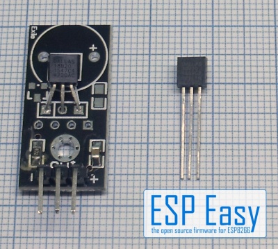
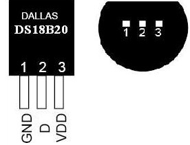
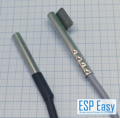
The DS18B20 manufactured by Dallas and Maxxim is a very simple to use temperature sensor with a tolerance of +/- 0.5°C. (Remember: Cheap remakes from chinese market might have bigger tolerance.) It's advantages: Very simple to use due to "One Wire" data protocol. Chainable, it is possible to chain up to 100 sensors on one cable (remember ESPEasy has 12 tasks max...). No calibration necessary if the tolerance fits your needs as the sensor gives digital data directly. Many forms availlable from bare chip to waterproof and tube sensors.
  Every DS18B20 has a unique adress burned in at production time.
  This UID (Unique IDentifier) is used to tell the sensors apart on one single cable.
Precautions
The DS18B20 runs well on 3,3V so no level shifter or special power supply is needed.
The sensor needs a pull up resistor. If you use the breakout board type the resistor usually is already on the board. This gets you into problems if using several DS18B20 breakout boards- As there should be only one resistor on the whole line you might have to remove resistors leaving just one at one end of the line.
Cabling: Do not use very thin cabling! Tested with a 3*0,14mm² cable the length with 5 Sensors was 10 meters, longer cabling did not work. Use a phone cable (2*2*0.6mm²) instead if you need long distances up to 50..100 meters. remember: One (!) pull-up resistor for the whole line!
The preferred structure is a straight line. If possible avoid "stubs". If necessary it can be cabled in a "star" infrastructure. But be aware that stubs and star form reduce the possible cable length.
Hardware
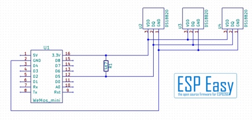
Connecting the DS18B20 is done easily. Just connect it as shown in the schematic:
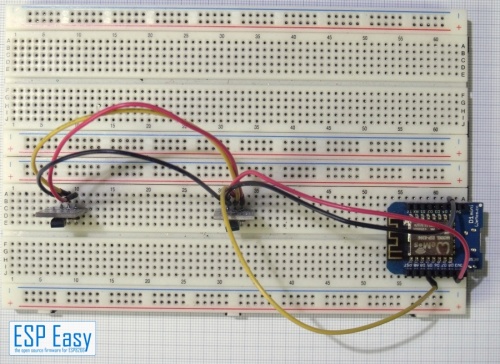
As you can see the sensors are just lined up, no aditional "trick work" necessary. Testing was made with a simple breadboard circuit:
ESPEasy
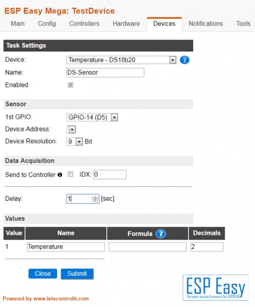
Chose a task to set up the DS18B20.
There is no device address at this time, they will show up later. Set the GPIO field to the GPIO you connected the sensor(s) to.
Additional setting
Device resolution: The device resolution can be set. The lower the resolution the accuracy decreases and the speed increases. As temperatures do not change very fast usually a high accuracy can be choosen without problem.
Submit the settings to the ESP.
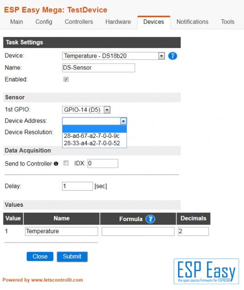
Now the Device address field shoud get alive.
If you have only one DS18B20 connected just chose the single address shown and submit. If you have several DS18B20 it's a good idea to connect one by one and note the addresses before installing all in a line - it gets confusing otherwise.
  Remeber you have to setup a task for every single sensor on the line. They have all same settings besides
  the device address and name.
Now it should like this in your device list:
Too late - all DS18B20 installed
And now it gets confusing. Which address is which sensor? A simple trick helps out.
Set up a task for every sensor, just name them DS1, DS2, DS3.....
Now take one sensor between your finger tips for half a minute and watch the values. One value should raise as your fingers usually are more warm the the air around. Now you may name it to a meaningfull name like "Livingroom" or whatever.
Calibrating
See "Basics: Calibrating" for further information [link]
Hints
(To be breadboard checked, not tested yet. Can the plugin handle that?)
If you need a star infrastructure or stubs or if you need just longer cabling there is a way out. One line runs on one GPIO. But nobody said you can't use two GPIO's.... If the cabling gets too long or you have too much stubs or star cables try to split into two circuits. Place the ESP in the mid and cut the line into two circuits, for example "Ground Floor" and "1st Floor". Use two GPIO's, one for every circuit.
Troubleshooting
Usually the DS18B20 works without issues. It's also usual that most problems result from cabling mistakes... With long cabling you might get wrong data sometimes. It might be helpfull to reduce the resistor a bit, 2,2 KOhm is lowest possible.
If nothing works disconnect all sensors from line and connect back one by one, checking every time. Cable may be too long (or too thin for the given distance). Keep cabling away from other cables to avoid interferences. If necessary place a 10µF capacitor on the sensors between 3,3v and Gnd.
