Difference between revisions of "Dallas DS18b20"
| Line 44: | Line 44: | ||
== ESP Connexio == | == ESP Connexio == | ||
Syntax: DallasRead "var" | Syntax: DallasRead "var" | ||
| − | |||
| − | |||
| − | |||
| − | |||
| − | |||
| − | |||
| − | |||
| − | |||
| − | |||
| − | |||
| − | |||
| − | |||
| − | |||
| − | |||
| − | |||
| − | |||
| − | |||
| − | |||
| − | |||
| − | |||
| − | |||
| − | |||
| − | |||
| − | |||
| − | |||
| − | |||
Revision as of 21:57, 12 May 2017
Contents
Introduction
The ESP module can read a Dallas DS18b20 sensor using the Dallas OneWire protocol.
The Dallas sensor needs to be connected to a configurable GPIO on the ESP module. In case you have a simple ESP-01 module, it's best to use the GPIO-2 pin.
Hardware
The Dallas sensor can be connected directly to an ESP module. It only needs a 4k7 resistor connected between VCC and the GPIO datapin.


Design considerations
Here is an example of the use of an ESP-01. This little board requires an additional FTDI board for programming. Be sure to use 3.3 volt types only. Also two buttons are used for programming, one to enter the programming mode and one to reset. In order to program the ESP-01, first press the GPIO00 button and hold it while pulsing the reset buttons. After that you can release the GPIO00 button. In most cases it is necessary to place an electrolytic capacitor of 47 to 100 uF and a ceramic capacitor of 100nF over the power lines, as close as possible to the ESP-01. The 1-wire line requires a pull-up resistor. Values between 4k7 and 10k are fine. More DS18B20s can be hooked-up to the same data line. Cable lengths of several meters up to several hundreds of meters are allowed, but special design rules with respect to the use of long lines are in place. https://www.maximintegrated.com/en/app-notes/index.mvp/id/148 for more details. Be reluctant towards the use of GPIO00. At startup, this pin require a high level for proper startup.
Software
Custom Sketch
ESP Easy
Use the device tab on the ESP Easy webinterface and create a new task by editing one of the available tasks. Select "Dallas DS18b20" from the dropdown box.
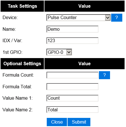

Enter the IDX found in the Domoticz device page. Also select the GPIO pin that you have used to connect the dallas sensor. That should be all.
Optional settings
And the final result if using Domoticz:


ESP Connexio
Syntax: DallasRead "var"