User:Shardan/IR-Transceiver
Contents
IR-TXRX Matchbox Sized
The goal of this project was to create a somewhat small infrared device that can be used as IR-transmitter, receiver or both.
The whole circuit fits into a matchbox. It can hold two or four IR LED’s depending on the IR power and scattering you need.
On top the PCB holds a TSOP4838 IR receiver so it can be used as a receiver for standard IR remotes.
Prerequisites
The circuit needs an external 5V power supply.
Please remember that the LED pulses take up some power!
Do not use a cheap power supply. It should give a reliable power of 1…1,5 A at least.
I used SMD parts to keep sizes small. Even using the 1206-size (3.2 x 1.6 mm²) this needs
calm hands and a fine soldering iron (pencil tip type) to solder these tiny parts.
All capacitors are ceramic types from the X5R and X7R range.
Do not use film capacitors or electrolytic/tantal capacitors. They are not suitable here.
Depending on your needs you may use 2 or 4 IR-LEDs.
(D1/D2 together or, D3/D4 together, or all four). Both sizes (3mm and 5mm) are usable.
If you need to scatter over a bigger area, place all 4 diodes and bend them a bit to left and right to get a good IR coverage of the room.
Schematics
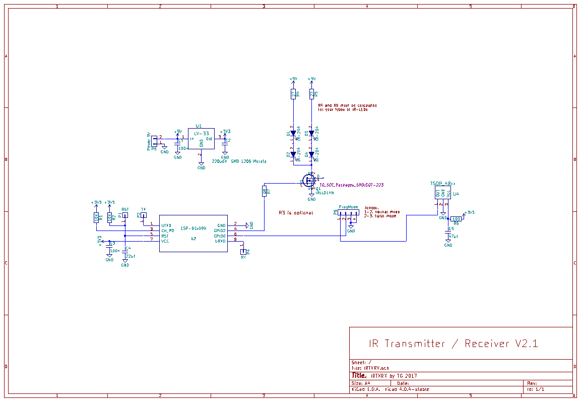
The IR-TXRX uses the ESP-01, the smallest ESP-board. It provides two GPIO’s sufficient for sending and receiving IR.
The voltage regulator LV-33 (LF-33CDT) supplies 3.3V for the ESP.
R1 and R2 are pull-up resistors for Reset and CH_PD (Chip-Enable).
C3 is a blocking capacitor for the ESP-01.
C4 pulls down the reset for a short moment after switching on, this giving time to get stable power
R7 is a 0 Ohm resistor, just a bridge to hop over a copper track. This allows using of a single sided PCB.
R6/C5 are used as a filtering for the power supply of the TSOP4838 Receiver.
The “Prog-Mode” pinheader P6 uses a jumper. In use mode the jumper is seated on pins 1+2.
This connects the TSOP to GPIO0. For flashing the ESP in-circuit, place the jumper on pins 2+3.
Pin 4 provides Ground for the flash adapter.
The IRLL014N FET provides the current needed for the LEDs.
R4 and R5 limit the LED current. The value of 27 Ohm is calculated for IR-204 diodes.
It must be adapted to other LED types.
PCB
 ]]
]]
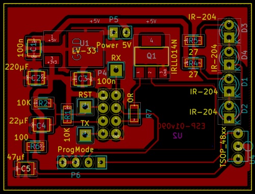
The PCB is a single sided type, kept relatively simple.
The PDF provided has an exact 1:1 view.
Printed with 100% sizing you may use it for PCB etching or give it to a manufacturer.
A solder resist mask for manufacturing and a component placement spec are also provided.
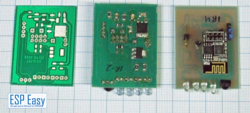
The PCB, empty – soldering side and top side of a completed device
Building the Circuit
This circuit is not too difficult to set up.
Solder all resistors first, capacitors second.
Then place the LV-33 regulator and the FET.
 Remember: FET’s are sensitive to static discharge.
 Always follow the ESD-rules so the FET (and the ESP, too) don’t get damaged.
It is possible to place the ESP-01 directly. If you are not experienced with building such circuits
a female 2x4 pin header is recommended so you can swap the ESP easily.
After soldering all SMD parts the pin headers and the TSOP4838 should be placed.
 Do NOT place the LEDs for now!
 The LEDs get fully driven if a ESP without firmware is used.
 The LEDs usually send pulses. For this purpose they can be driven with very high current
 which will damage them if used permanently for some minutes while flashing.
After soldering check your PCB very carefully for unwanted “bridges”, connections between pins that should not be connected.
A steel needle or a sharp cutter knife helps to get rid of such bridgings.
If nothing helps use desoldering wick to get rid of solder tin.
Flashing
 Do not connect power now! Just prepare power so you can switch on fast.
 A switched outlet helps with that.
 - Place a jumper cap to pins 2+3 of the P6 “Prog Mode” header.
 - Connect your programming adapter to TX and RX pin. Use pin4 of P6 “Prog Mode” for Ground.
 - Start the flash tool program, select the 1024-binary of ESPEasy and start flashing.
 - Now power up your circuit immediately.
After flashing succeeded power off the circuit, disconnect the programming adapter.
Set the jumper to pin 1+2 of P6 to connect the TSOP.
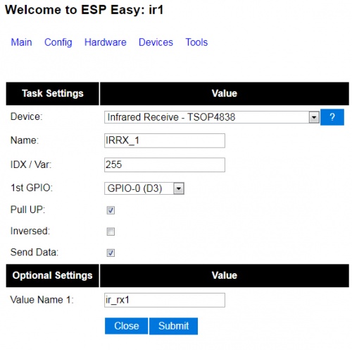
ESPEasy Settings
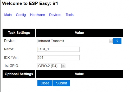
The settings use standard ESP devices from the standard binary.
We need two devices, one for sending, one for receiving (if you use both..).
Transmitter device:
Receiver device:
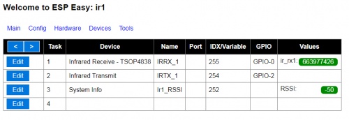
If your settings are done the device list should look like this
(I use a RSSI value for some purposes in my system, it is optional for you)
Now you may solder your LEDs to the PCB.
Using the IR-TXRX Receiver
The receiver can be used as every other device giving back a number value.
Check which value you get from what key on your IR remote.
If you get the Value “12345678” you may use it for actions in your home control.
Just make something like
  IF value=12345678 then
    <action for this value>
  ENDIF
Using the IR-TXRX transmitter
For this you have to send a http command to your IR-TXRX.
The easiest way is to get the IR-sequences from the genuine IR remote.
I’ve used an Arduino Uno with the same TSOP4838 receiver and the IRrecvDumpV2.ino sketch to decode my remotes.
For the most remotes this sketch gives back three parameters:
 - Encoding type, one of the following: NEC, JVC, RC5, RC6, SAMSUNG, SONY, PANASONIC
 - Value: A hexadecimal number representing the code send.
 - Bitlength: How many bits the code contains.
It may happen that a remote shows a “unknown” with the Arduino decoding. In this case you have to use raw codes, this is not covered here.
To send the code use a simple http request:
http://<ip-addr. of your device>/control?cmd=IRSEND,<Encoding>,<Value>,<Bitlenght>
For example it may look like this:
http://<ip-addr>/control?cmd=IRSEND,NEC,0FB123C7,32
This sends the code 0FB123C7 with 32 bit in NEC encoding.
Integrating to FHEM
For those using FHEM with the ESPEasy bridge integrating is very easy.
If your ESPEasy bridge is already configured the device is recognized automatically.
Define a notify as follows:
define n_key1 notify <trigger-RegExp> set ESPEASY_<devicename> IRSEND NEC 0FB123C7 32
With triggering this notify by an FHEM-event you wills end the given code.
A more common form is
define n_key1 notify <trigger-RegExp> set ESPEASY_<devicename> $EVENT
You can call the notify with an event-value containing the sending command.
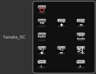
This is useful if you want to build complete remote controls like this (from my fhem.cfg):
  define Yamaha_RC remotecontrol
  attr Yamaha_RC group g_OfficeRemote
  attr Yamaha_RC rc_iconpath icons/remotecontrol
  attr Yamaha_RC rc_iconprefix black_btn_
  attr Yamaha_RC row00 IRSEND NEC 7E81542B 32:POWEROFF3, :blank, :blank
  attr Yamaha_RC row01 IRSEND NEC FE801A64 32:FM, IRSEND NEC FE80DAA4 32:CHUP2, IRSEND NEC FE807A04 32:CHDOWN2
  attr Yamaha_RC row03 IRSEND NEC 5EA198E7  32:AUDIO,:blank, IRSEND NEC 5EA183FC 32:2ND_AUDIO
  attr Yamaha_RC row04 IRSEND NEC 5EA15827 32:VOLUP, IRSEND NEC 5EA1D8A7 32:VOLDOWN, IRSEND NEC 5EA13847 32:MUTE
  attr Yamaha_RC row05 IRSEND NEC 5EA15926 32:SPEAKER1, :blank, IRSEND NEC 5EA1D9A6 32:SPEAKER2

  define notify_Yamaha_RC notify Yamaha_RC set ESPEasy_ir1 $EVENT
  attr notify_Yamaha_RC room Office
The “POWEROFF3”, “FM”,”CHUP2” and so on are just predefined buttons from FHEM.
This sets up a small remote for my Yamaha Receiver:
Have Fun!
Files
File:User-Shardan IRTXRX Documentation WithPCB.pdf
File:User-Shardan Schematics IR-TXRX.pdf
File:User-Shardan PCB-doc.pdf