User:Shardan/IR-Remote
The goal of this project was to create a small infrared device that can be used as IR-transmitter, receiver or both.
The whole circuit fits into a small ABS case. It can use two or four IR LED’s depending on the IR power and scattering you need.
On top the PCB includes a TSOP4838 IR receiver so it can be used as a receiver for most usual IR remotes.
The update to a new version was necessary as the old ESP-01 slowly gets outated and 1 MB memory runs into problems nowadays.
Contents
Precautions
The circuit needs an external 5V power supply.
Please remember that the LED pulses take up some power!
Do not use a cheap power supply. It should give a reliable power of 1…1,5 A at least.
I used SMD parts to keep sizes small. Even using the 1206-size (3.2 x 1.6 mm²) this needs
calm hands and a fine soldering iron (pencil tip type) to solder these tiny parts.
All capacitors are ceramic types from the X5R and X7R range.
Do not use film capacitors or electrolytic/tantal capacitors. They are not suitable here and won’t fit on the PCB.
Depending on your needs you may use 2 or 4 IR-LEDs.
(D1/D2 together or, D3/D4 together, or all four). Both sizes (3mm and 5mm) are usable.
If you need to scatter over a bigger area, place all 4 diodes and bend them a bit to left and right to get a good IR coverage of the room.
Schematics
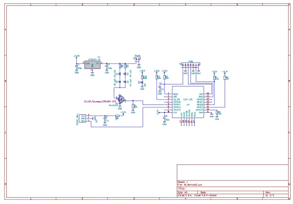
For printout schematics as a pdf file: File:Schematics.pdf
The IR-Remote uses the ESP-12E. An older ESP-12 can be used, also a ESP-07S with external antenna if necessary.
The voltage regulator LV-33 (LF-33CDT) supplies 3.3V for the ESP.
C1 and C3 are filtering capacitances to keep the LF-33 calm.
C5 is a decoupling capacitor for the ESP-12 keeping high frequencies off the circuit.
C4 pulls down the reset for a short moment after switching on, this giving time to get stable power.
R1/C2 are used as a filtering for the power supply of the TSOP4838 receiver.
R5,6,7 and R9 are pullup resistors, R8 is a pulldown resistor for setting the normal work mode of the ESP.
The “Prog” pinheader J2 includes all necessary pins for flashing ESPEasy to the chip.
Use a jumper on pin 6 & 7 to set flashing mode. Connect the flasher to pin 3 (Tx of ESP),
pin 4 (Rx of ESP) and pin 5 (Gnd). You may reset the ESP by shortening pins 1 & 2 for a second.
The IRLL014N FET provides the necessary current for the LEDs.
R2 and R3 limit the LED current. The value of 27 Ohm is calculated for IR-204 diodes.
It must be adapted to other LED types.
R10 and LED D5 are just a "power on" indicator and can be omitted.
The PCB
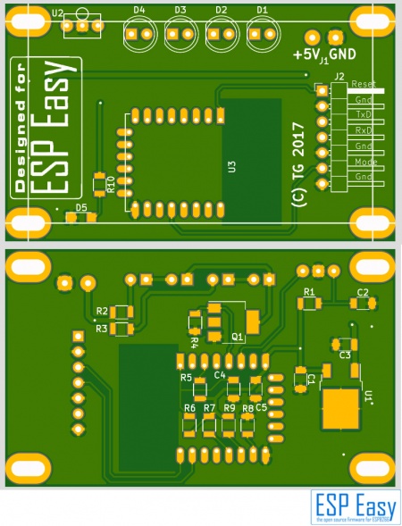
The PCB is made by a professional company, including gold plated pads and tracks, silk printing on both sides,
vias and testing. No, not cheap. Anyways, I’ve learned from experience that cheap made PCBs
come with a lot of problems. Building the PCB without contacted vias is a frustrating pain.
Ask the author for PCBs.
Building the Circuit
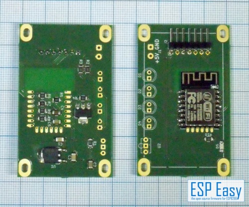
This circuit is not too difficult to set up. Solder all resistors first, capacitors second.
then place the LF-33 regulator and the FET. Remember: FET’s are sensitive to static discharge.
Always follow the ESD-rules so the FET (and the ESP, too) don’t get damaged.
To get the ESP-12 aligned perfectly a simple Trick does the job: I used a copper wire pushed through the
top left and bottom right hole of the ESP and the PCB. This keeps the ESP in place exactly for soldering
two or three pins to the PCB. Then remove the wire and solder all pads.
After soldering all SMD parts the pin headers and the TSOP4838 should be placed.
After soldering check your PCB very carefully for unwanted “bridges”, connections between pins that
should not be connected. A steel needle or a sharp cutter knife helps to get rid of such bridgings.
If that does not help use desoldering wick to get rid of solder tin.
Adding the LEDs
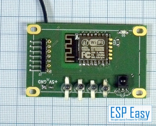
For the case I used the LEDs should be mounted about 2 mm higher above the PCB.
A simple trick helps:
Put some short pieces of matches under the LEDs.
Flashing
Use a jumper on pin 6 & 7 to set flashing mode. Connect the flasher to pin 3 (Tx of ESP),
pin 4 (Rx of ESP) and pin 5 (Gnd). Start flashing on the computer and shorten pins 1&2 for a second
with a screw driver or similar to reset the ESP.
After flashing has succeded, don’t forget to remove the jumper (and don’t ask why I insist on that).
ESPEasy Settings
The settings use standard ESP devices from the standard binary.
We need two devices, one for sending, one for receiving (if you use both..).
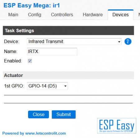
Transmitter device:
Settings are quite simple for the IR transmitter:
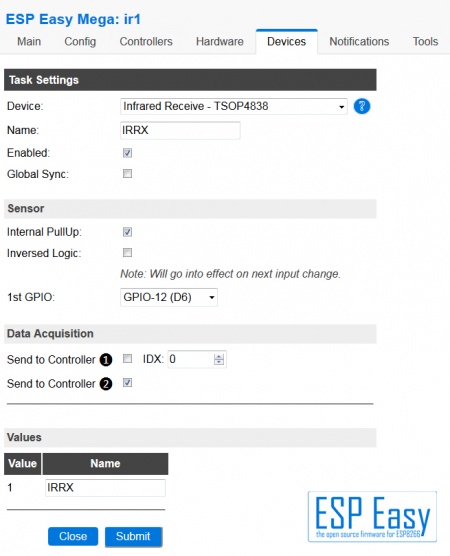
Receiver device:
As simple as the transmitting device: the receiving part:
Mounting into the case
There are so many possibilities to mount this device into a case..
LEDs straight upright or to the side… some hundred cases to chose from....chose your poison.
I’ve chosen a really cheap case that just fits the PCB. It’s available from AliExpress, made by SZOMK, type AK-S-16.
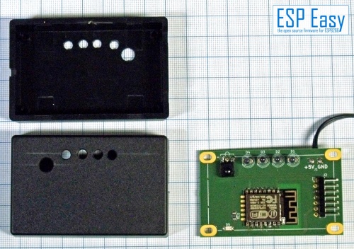
Drilled the holes for LEDs and Receiver, cut a small outlet gap for the power cable – that’s all.
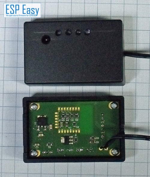
Using the IR-TXRX Receiver
The receiver can be used as every other device giving back a number value.
Check which value you get from what key on your IR remote.
If you get the Value “12345678” you may use it for actions in your home control.
Just make something like
 IF value=12345678 then
    <action for this value>
 ENDIF
Remark: The value given back might have changed meanwhile into something better defined.
Anyways it can be used in the same way.
Using the IR-TXRX transmitter
For this you have to send a http command to your IR-TXRX.
The easiest way is to get the IR-sequences from the genuine IR remote.
I’ve used an Arduino Uno with the same TSOP4838 receiver and the IRrecvDumpV2.ino sketch to decode
my remotes. For the most remotes this sketch gives back three parameters:
 - Encoding type, one of the following: NEC, JVC, RC5, RC6, SAMSUNG, SONY, PANASONIC
 - Value: A hexadecimal number representing the code send.
 - Bitlength: How many bits the code contains.
It may happen that a remote shows a “unknown” with the Arduino decoding. In this case you have
to use raw codes, this is not covered here. To send the code use a simple http request:
http://<ip-addr. of your device>/control?cmd=IRSEND,<Encoding>,<Value>,<Bitlenght>
For example it may look like this:
http://<your IR's IP>/control?cmd=IRSEND,NEC,0FB123C7,32
This sends the code 0FB123C7 with 32 bit in NEC encoding.
Integrating to FHEM
For those using FHEM with the ESPEasy bridge integrating is very easy and gives a lot of fun as
building a remote control is easy with FHEM:
If your ESPEasy bridge is already configured the device is recognized automatically as soon as
the controller is defined in the IR-Remote’s controller settings.
Define a notify as follows:
define n_key1 notify <trigger-RegExp> set ESPEASY_<devicename> IRSEND NEC 0FB123C7 32
With triggering this notify by an FHEM-event you will send the given code.
A more common form is:
define n_key1 notify <trigger-RegExp> set ESPEASY_<devicename> $EVENT
You can call the notify with an event-value containing the sending command.
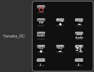
This is useful if you want to build complete remote controls like this (from my fhem.cfg):
 define Yamaha_RC remotecontrol
 attr Yamaha_RC rc_iconpath icons/remotecontrol
 attr Yamaha_RC rc_iconprefix black_btn_
 attr Yamaha_RC row00 IRSEND NEC 7E81542B 32:POWEROFF3, :blank, :blank
 attr Yamaha_RC row01 IRSEND NEC FE801A64 32:FM, IRSEND NEC FE80DAA4 32:CHUP2, IRSEND NEC FE807A04 32:CHDOWN2
 attr Yamaha_RC row03 IRSEND NEC 5EA198E7  32:AUDIO,:blank, IRSEND NEC 5EA183FC 32:2ND_AUDIO
 attr Yamaha_RC row04 IRSEND NEC 5EA15827 32:VOLUP, IRSEND NEC 5EA1D8A7 32:VOLDOWN, IRSEND NEC 5EA13847 32:MUTE
 attr Yamaha_RC row05 IRSEND NEC 5EA15926 32:SPEAKER1, :blank, IRSEND NEC 5EA1D9A6 32:SPEAKER2
 define notify_Yamaha_RC notify Yamaha_RC set ESPEasy_ir1 $EVENT
The “POWEROFF3”, “FM”,”CHUP2” and so on are just predefined buttons from FHEM; read from the path given in the iconpath attribute.
This sets up a small remote for my Yamaha Receiver:
