PIR Sensor
Contents
Introduction

PIR sensors (Pyroelectric InfraRed sensors, also Passive InfraRed sensors) are used to detect moving heat sources, for example a human body.
They are used for stairway lighting, alarm systems and similar.
How does it work?
The PIR sensor consists of several infrared detectors that build "zones".
If a heat source like a human moves from one zone to another it is detected
and the sensor triggers.
Precautions =
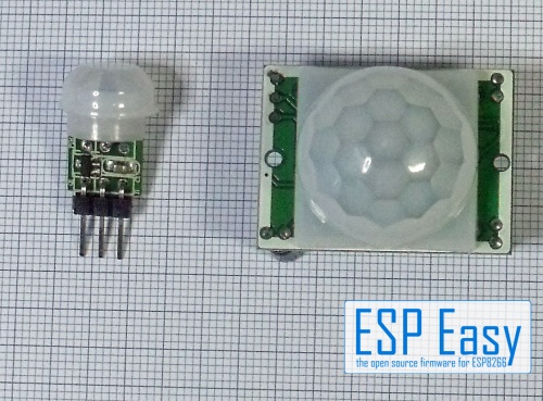
Both sensors shown need 5V..12V power supply. They have a 3,3V voltage regulator on board.
Level converting is not needed. If you use other PIR sensors please check if they have
3.3V - outputs or if level converting is necessary.
Hardware
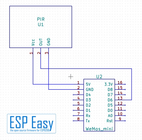
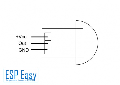
For connecting follow the given schematics as shown in the pictures.

The MiniPIR sensor has no further hardware settings.

The HC-SR501 has several settings:

You may adjust the sensitivity and the "hold delay", the time the signal stays high
after a moving person was detected. Rotating the potentiometer clockwise increases the hold delay time. At maximum value the hold delay time can be many minutes.
The jumper selects the trigger mode. If it is set to "Single Trigger" the sensor triggers once
and then waits until the delay time is over before you can trigger it again.
If you select the "Repeated Mode" (retriggering), every detection restarts the delay time, no matter
if it still was running or not.
ESPEasy
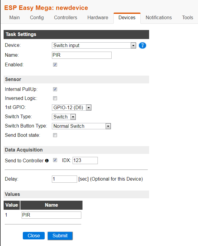
As these sensors give a logical high/low signal they are connected as a switch.
Set up the ESPEasy task according to the screenshot.
If you have chosen other GPIO pins set them accordingly.
In order to prevent the ESP Easy from sending an update every second, flooding your home automation system, you can set the delay higher.
A change in value, in case motion is detected, will be send anyway. Even if the delay is not yet expired.

False Positives
Electronic Problems
Some people reported many false positives with the HC-SR501.
An additional 10 KOhm pull-up resistor from the Output to 3,3V might help.
Also a capacitor of 10...100µF as near as possible at the Vcc/Gnd-pins helps taming false positives.
Other Reasons
A reason for false positives might be sunlight. As the sun moves, the sunrays move from one detection zone to another.
Try to place the sensor to another plkace, avoid sunlight.
Do not place the sensor into direct sunlight as the sensor might go blind if it gets warmed up.
See the wiki for more information: Basics: Taming false positives