Relais
Introduction
The ESP can control a relay using one of it's GPIO pins. All relay boards that work with Arduino should also work with the ESP module. Note this is only a possible application of the ESPs ability to send a logic 1/0 (TTL@3.3V) on a GPIO. These relay are usually available as 1,2,4,8,16 Relay modules and work electromagnetically.They can switch both AC/DC(or imitate a button press of a remote for example) as they are "power operated mechanical switches". Each relay has the screw terminal. The middle one is usually "always connected" terminal. The NC contact will be connected to the middle terminal when the relay is not powered. The NO is connected when the relay is powered and activated. Note that there are "active high" and "active low" versions of these relays.
Please also read this usefule info on relays ("basic") here: [1]

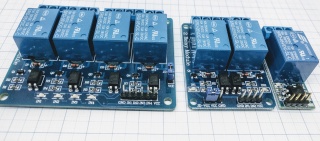
Typical relay boards widely available on ebay/ali/amazon
Hardware
Connect the relay board to one of the GPIO pins on the ESP module. In case of ESP-01, we will use GPIO-2.It is also possible to connect Relays to I/O I2C port expanders ( PCF8574 + MCP23017 are supported by ESP Easy)
Caution needs to be applied when choosing the GPIO to use. There can be issues on boot as the pins go through defined boot states before taking the state defined under the hardware tab, causing relays to trigger during boot (or reboot which can happen pretty often).
If possible avoid GPIOs 2,3,4,15,16. If the "flicker" during reboot does not matter to your application it is still possible to use the before mentioned GPIO. A great way to avoid this problem is the use of the I2C I/O expanders.
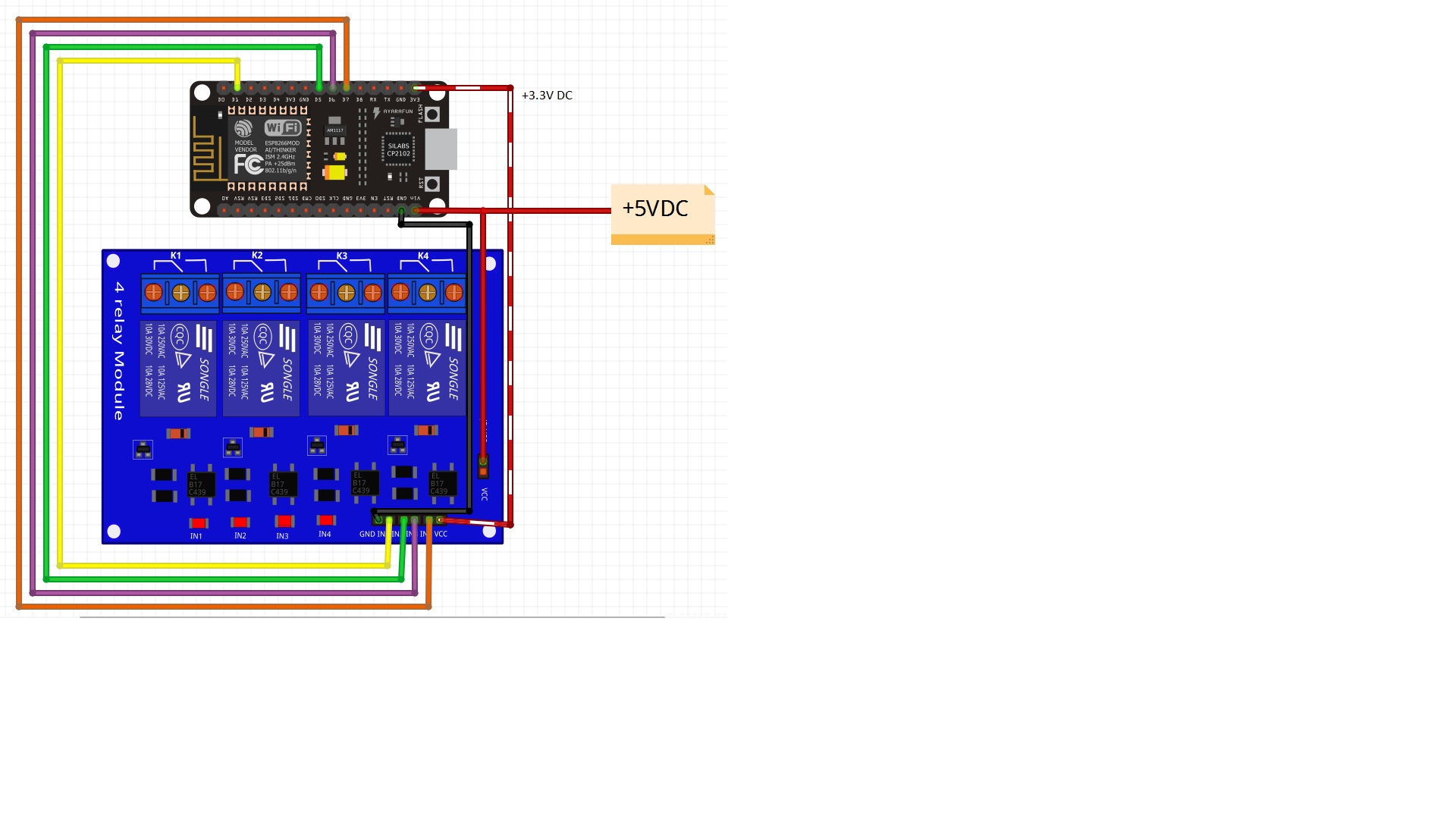
Most of the relay boards expect a 5V ttl signal like many arduino boards provide on their output pins. But 3V3 logic should also work. If your relays require a 5V TTL level, it is possible to use a level shifter. From 2 Relays-Board+ there is usually a second Vcc pin header with two pins connected by a jumper. If the jumper is connected it means that the relay power is drawn from the same power source as the logic (usually the ESP 3.3V). This is very bad practice and should be avoided as it can lead to instable behaviour. You can however feed the Relay from a second power source by removing the jumper and connecting VCC-JD to a separate power source (5V). GNDs should be tied together.
 NodeMCU connected to a 4 relay board sharing a 5V PSU
If you don't need expandability (or are lazy to solder/breadboard) there are plenty of boards containing relays (Sonoff, Electrodragon, linksprite)
![]()
For special applications it is well worth looking beyond electromagnetic Relays. If only AC needs to switched on/off it is possible to use solid state relays which rely on a triac with a zero crossing detection to switch power (yes no current in the moment of switchting)and there are no mechanical moving parts that can fail or contacts that stick. When switching higher currents make sure to have appropriate cooling. They are available with Logic level input of 3-32 VDC. Be sure to ONLY switch AC of sufficient current, elsewise the triac can switch on but not off again.
module from pollin.de that can switch 5A @ 230VAC
module from pollin.de that can switch 20A @ 230VAC
Design considerations
- Be careful with these relais when you consider to connect them to mains. In that case, some of them are not safe to be used when they are in a circuit with parts that can be touched. For example, if you want to connect such a relay on an ESP that also controls a sensor that can be touched. - The tracks on the pcb are sometime not suitable to carry more than some 4 Amps. See also: http://www.desmith.net/NMdS/Electronics/TraceWidth.html or https://www.candorind.com/pcb-calculator/trace-width-calculator/
Software
ESP Easy
Strictly seen, Relays are not a plug-in driven device like most other devices. It is not necessary to have a task (item under Devices tab) for them to work
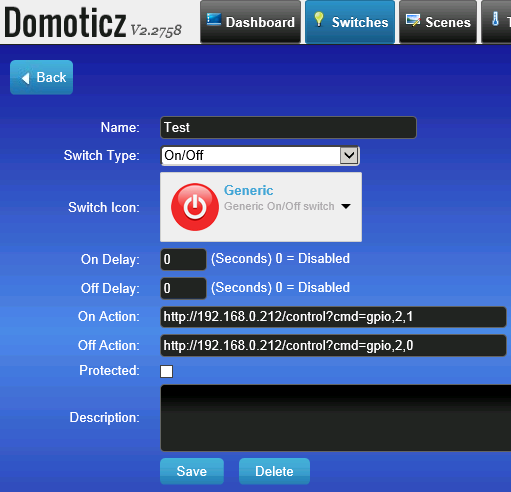
We can control the relay board with two simple http url commands:
http://<ESP IP address>/control?cmd=GPIO,<pin>,0
http://<ESP IP address>/control?cmd=GPIO,<pin>,1
Domoticz example:
ESP Connexio
Syntax: WiredOut 1,On/Off
