Hello,
Warning: first post!

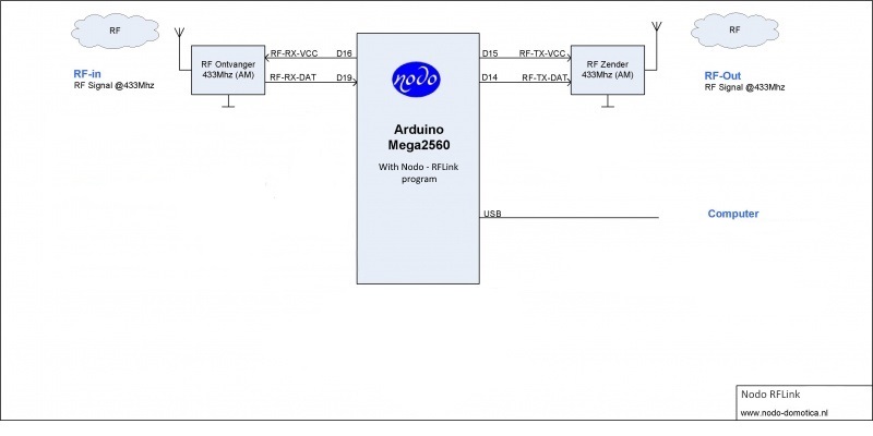
I began yesterday with experimenting with RFLink. I had first bought a set of cheap Chinese RF transceivers and later also bought RXB6 after reading the forums.
Experiments with RXB6
I first tried my experiment with RXB6 after wiring as per
http://www.rflink.nl/blog2/wiring, but to no avail. I then extended with the suggested enhancements of using capacitors to reduce noise, but I still got no signal at all. I added the antenna and the shield, but still no result. I stumbled upon this page:
https://diyprojects.io/how-build-rflink ... itIdWhKh3g. This one is also based on RFLink project but the wiring is a bit different. The author suggests wiring Vcc and Gnd near antenna as well. Is that needed? In any case, despite connecting that, my receiver refused to respond. I have attached the photos; if someone sees any obvious mistake, please let me know.
Experiments with cheap Chinese Set
This worked almost immediately, even without the antenna. (Soldering 17.3cm antenna didn't seem to make any difference, but then I was just testing it with 10cm distance.) I began getting data immediately although the protocol/device type received is a bit different. Is that common? For example, when I use 'SelectRemote', it actually shows PT2262 Protocol, and when I used BFT Remote control, it identified it as 'Keeloq'. Is that expected or is it noise coming in from the 'cheap' receiver?
Transmitter
This is where I am really stuck. What should be the range of the cheap Chinese transmitter with or without the antenna? I tested sending various commands back using the Protocol defined at
http://www.rflink.nl/blog2/protref, essentially using the received codes, but none of them worked. I tested at around 10cm distance also, but to no avail. At this point, I am not sure whether the transmitted is faulty, or my commands are wrong. Is there any way to test the transmitter? Are there any known codes/command that I could send to SelectRemote for example, that should work?
Thanks a lot for your help.
Kind regards,
Akash