I bought one of these a few days ago
https://www.aliexpress.com/item/4001232 ... 4c4dIETQ8P
A board with either 2+2, 4+4 or 8+8 IOs, WiFi, LAN. and/or either RS485 or CAN, supports Http, Https, MQTT, CoAP has Domoticz plugin and an extensive how-to Home Assistant support.
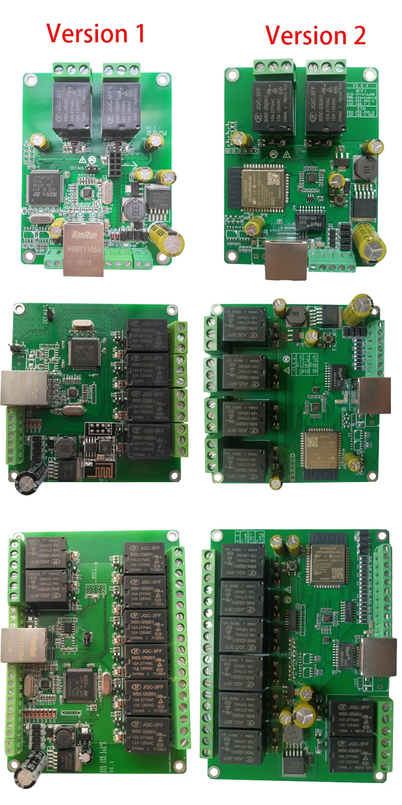
Initially those boards came with an STM processor + LAN chip and used an ESP-O1 for wifi.
In the last hardware revision both have been replaced by an ESP32 + LAN chip
I got the 8 I/O version (8xRelays + 8xInputs) but there are also 2 SPI chips (1 for the 8xOUT and another for the 8xIN) most likely due to the GPIO count of the ESP32 is less than the previously used STM
The so called SDK from the manufacturer is here :
http://www.dingtian-tech.com/sdk/
The User Manual (in the .zip) goes in depth about all aspects.
At a first glance seems to be a product targeted to "our crowd" well priced for what it does out of the box.
Of course ESPEasy is our goal, so in the next couple of days will see what needs to be supported before flashing it.
Time for some turkey left overs