Hi
I have a flow water sensor USN-HS21TA https://www.aliexpress.com/item/3269628 ... 4c4d1W1pgh
I have set up a Generic - Pulse counter
How to tune the device to get accurate measure?
Build: 20113 - Mega
Build Time: May 3 2021 11:31:57
Binary Filename: ESP_Easy_mega_20210503_normal_ESP8266_4M1M
Pulse high or low or something else?
Debounce Time (mSec): how to choose a value?
Counter Type: I set Delta...?
Formula: in the doc it's writen F=10Q, so I set %value%*10
Do I have to set the same formula in the Total? or the Total is the Total of Count after the formula?
Flow water sensor tuning
Moderators: grovkillen, Stuntteam, TD-er
Re: Flow water sensor tuning
i did some more digging and testing...
I understood that F=10Q means F (Hz) =10Q (l/min)
So aAs my sensor is for 1 L/min to 30 L/min, I have a frequency from 10 Hz to 300 Hz, so a period form 100 ms to 3,3 ms
A rule of thumb given here Re: Pulse Counter Problem gives debounce time is 1/10 of the pulse low
so less than 3,3 ms for me I set 33... (x10)
I did some testing with Pulse Low, I seems to give twice the good value
I put Pulse High, It was ok with 10 liters
How to make it better? Stability, not always the sames vales. Perhaps I don't put enough water for the testing (5 liters)
I've tried the debug as mentioned in the docs but did catch any log with P003
Do have I to set something in the Formula in the bottom of the Device? How ESP Easy knows how to transform pulse in liters?
I understood that F=10Q means F (Hz) =10Q (l/min)
So aAs my sensor is for 1 L/min to 30 L/min, I have a frequency from 10 Hz to 300 Hz, so a period form 100 ms to 3,3 ms
A rule of thumb given here Re: Pulse Counter Problem gives debounce time is 1/10 of the pulse low
so less than 3,3 ms for me
I did some testing with Pulse Low, I seems to give twice the good value
I put Pulse High, It was ok with 10 liters
How to make it better? Stability, not always the sames vales. Perhaps I don't put enough water for the testing (5 liters)
I've tried the debug as mentioned in the docs but did catch any log with P003
Do have I to set something in the Formula in the bottom of the Device? How ESP Easy knows how to transform pulse in liters?
Re: Flow water sensor tuning
The formula option in the counter may have a slight unexpected side-effect.
The formula does change the value in the task value array.
So it may be applied twice when the last value is restored at boot. (e.g. after a crash)
Not sure if the formula option is the best solution here as it is ran when the PLUGIN_READ function is called of the task.
This is called when:
- Interval set in the task settings has expired
- TaskRun is called
What is your intention with the flow sensor? To actually measure the flow, or to count water consumption?
10 pulses/sec => 10 liter/min, then your flow sensor reports 60 pulses per liter.
So each pulse is 1/60 liter.
I guess it may be a more 'stable' result if you measure over a longer period, but just to get a feeling for it, you may want to initially set the "interval" of this pulse task to 1 sec.
The "count" value (when selecting a "Counter type" with "delta" in it) is the change since the last update. (interval)
So with the interval set to 1 second, you simply get the "frequency" in the "Count" field.
If you measure over a longer period, you will get a more stable result as output value, but then you need to convert the value.
Since the 'count' value isn't that useful to keep and restore if you update it every N seconds, you can use the formula field of it.
e.g. "%value% / 60" for using an interval of 60 seconds.
About the difference between counting the rising and falling edge.
If there is a difference here, it might be the "high" or "low" value isn't really close to 3v3 or 0V respectively.
So you may want to have a look at that.
Maybe you use a long cable and the cable may pick up some noise when carrying a low signal value?
In this case I guess it is better to simply trigger on the "rising edge".
The reason for this is that the initial change of a signal may be fast, but then the changing rate slows down.
So it may be relatively long in a state between a logical "high" or "low" state and then it is better to have a "high" signal than a "low" signal during this state of slowly changing voltage.
Noise is relatively small compared to a "high" signal, while it can be significant compared to a "low" signal.
Re: Flow water sensor tuning
Thanks TD-er for your reply
So, 1 pulse = 1/6 liter => 1 liter = 6 pulse
So If I put 1 liter into the sensor, I think, I should get 6 pulses
Prod:
High ~ 3,45
Low ~0 V
Sensor powered to the 5 V => 3,7 V in fact
Test:
High ~ 4,35
Low : I’ve forgotten to measure it…
Sensor powered to the 5 V => 4,95 V in fact
Anyway, I think I have a clear difference between high and low.
The high is greater than 3v3 ; is this a problem?
Some pictures:
Regarding the deboucing, as there is 1 pulse/sec = 10 l/min and the max is 30 l/min, so it is 3 pulse/sec, so 333 ms between each pulse, with the rule of thumb, I could start around 33
The objective is to measure how much water I put in my garden, so it is more consumption than flow, event though, I need the flow to define the duration of the next watering. All of this could be computing after.What is your intention with the flow sensor? To actually measure the flow, or to count water consumption?
I’m going to remove them, and put some computing in the rule and in DomoticzNot sure if the formula option is the best solution here
I understand it is more accurate on a long period, so I set 10 sec; is it enough to get an accurate measure, or it will be better with more, like 30 sec?interval
For this sensor the Formula is “F=10Q”, so 1 pulse/sec = 10 l/min and not “10 pulses/sec => 10 liter/min”. Am I right?10 pulses/sec => 10 liter/min, then your flow sensor reports 60 pulses per liter.
So each pulse is 1/60 liter.
So, 1 pulse = 1/6 liter => 1 liter = 6 pulse
So If I put 1 liter into the sensor, I think, I should get 6 pulses
I made some measures. I have 2 systems, 1 for testing (only one sensor) and 1 for the production (several sensors) and they have different power. So I’ve got different values!About the difference between counting the rising and falling edge.
If there is a difference here, it might be the "high" or "low" value isn't really close to 3v3 or 0V respectively.
So you may want to have a look at that.
Prod:
High ~ 3,45
Low ~0 V
Sensor powered to the 5 V => 3,7 V in fact
Test:
High ~ 4,35
Low : I’ve forgotten to measure it…
Sensor powered to the 5 V => 4,95 V in fact
Anyway, I think I have a clear difference between high and low.
The high is greater than 3v3 ; is this a problem?
The cables are around 40 to 50 cm. Are they long or not?Maybe you use a long cable and the cable may pick up some noise when carrying a low signal value?
In this case I guess it is better to simply trigger on the "rising edge".
Some pictures:
- production
- Capture d’écran 2021-09-06 113648.jpg (237.24 KiB) Viewed 30657 times
- for testing
- Capture d’écran 2021-09-06 113908.jpg (59.75 KiB) Viewed 30657 times
- for testing
- Arrosage_20210905_223756.jpg (509.5 KiB) Viewed 30657 times
Re: Flow water sensor tuning
For "long" cables, you should consider the cable will work as an antenna and thus collect noise.
Tweaking with the debounce filter is one way, but I think it is better to filter using a small capacitor over the GPIO pin.
I noticed your flow sensor uses a hall-effect sensor, which already gives a clean signal.
So you may want to add a pull-up resistor and a small capacitor to it to filter out the noise.
You may however need to place the capactor close to the ESP. The resistor may already be present in your sensor. But if not, you may want to add it.
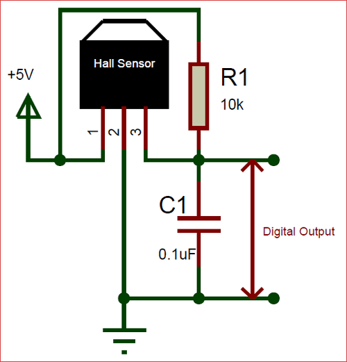
I think 100 nF as in the schematic here may be a bit too large, as it also limits the max. frequency you can use (in combination with the resistor)
The output of a hall-effect sensor is only slightly lower than the voltage you apply to it.
So it is best to add 2 resistors to make the voltage lower.
The GPIO pins of the ESP8266 seem to be 5V tolerant, according to some sources, but it is better to make the signal max 3V3.
So over the signal you can add 2 resistors, with a ratio of roughly 2:1 (e.g. 120k and 220k, since the signal itself is slightly less than 5V)
Sensor out ---- 120k ----- gpio ---- 220k ---- GND.
With a capacitor over the GPIO pin and the GND, you can probably ignore the debounce time.
Tweaking with the debounce filter is one way, but I think it is better to filter using a small capacitor over the GPIO pin.
I noticed your flow sensor uses a hall-effect sensor, which already gives a clean signal.
So you may want to add a pull-up resistor and a small capacitor to it to filter out the noise.
You may however need to place the capactor close to the ESP. The resistor may already be present in your sensor. But if not, you may want to add it.
I think 100 nF as in the schematic here may be a bit too large, as it also limits the max. frequency you can use (in combination with the resistor)
The output of a hall-effect sensor is only slightly lower than the voltage you apply to it.
So it is best to add 2 resistors to make the voltage lower.
The GPIO pins of the ESP8266 seem to be 5V tolerant, according to some sources, but it is better to make the signal max 3V3.
So over the signal you can add 2 resistors, with a ratio of roughly 2:1 (e.g. 120k and 220k, since the signal itself is slightly less than 5V)
Sensor out ---- 120k ----- gpio ---- 220k ---- GND.
With a capacitor over the GPIO pin and the GND, you can probably ignore the debounce time.
Re: Flow water sensor tuning
Thank!Sensor out ---- 120k ----- gpio ---- 220k ---- GND.
With a capacitor over the GPIO pin and the GND, you can probably ignore the debounce time.
Just to be sure
do you mean this
- 120k to 5V
- Screenshot 2021-09-06 153237.png (64.17 KiB) Viewed 30640 times
- 120k to GPIO
- Screenshot 2021-09-06 153411.png (291.77 KiB) Viewed 30640 times
Re: Flow water sensor tuning
More like the last one.
Just assuming the Hall-effect sensor itself already has a pull-up resistor between 5V and the output on the hall effect sensor (not on the GPIO side)
Just assuming the Hall-effect sensor itself already has a pull-up resistor between 5V and the output on the hall effect sensor (not on the GPIO side)
Re: Flow water sensor tuning
Thanks!
I'll do a test asap
I don't have 220k, not 120k (220 Ohm only)
I have 10k
Can I put a 10k and 2 x 10k instead?
I'll do a test asap
I don't have 220k, not 120k (220 Ohm only)
I have 10k
Can I put a 10k and 2 x 10k instead?
- Screenshot 2021-09-06 172125.png (216.19 KiB) Viewed 30629 times
Re: Flow water sensor tuning
3x the same resistor is OK, but.... the reason I took larger values is to make sure the pull-up resistor (if any) is a factor stronger than the ones on the output.
With 30k on the output, I don't know how much effect the pull-up resistor is.
With 30k on the output, I don't know how much effect the pull-up resistor is.
Re: Flow water sensor tuning
I did it with 140k and 280k ; I had 2 of them for testing (big size xW)
Nothing on the device.
The voltage seems to move from 2,65 to 3,35V between GND and GPIO
I try others circuit diagram???
Nothing on the device.
The voltage seems to move from 2,65 to 3,35V between GND and GPIO
I try others circuit diagram???
Re: Flow water sensor tuning
I did this one
https://components101.com/sites/default ... Sensor.png
with the sensor on 3v3 instead of 5v
The sensor still pulses... a lot
The voltage on the GPIO is from 0 to 3v3.
I'll try debounce
https://components101.com/sites/default ... Sensor.png
with the sensor on 3v3 instead of 5v
The sensor still pulses... a lot
The voltage on the GPIO is from 0 to 3v3.
I'll try debounce
Re: Flow water sensor tuning
What value of the capacitor did you use?
Also the hall-effect sensor should run on 5V, not on 3V3.
Also the hall-effect sensor should run on 5V, not on 3V3.
Re: Flow water sensor tuning
100nF
Is it a good one?
- Screenshot 2021-09-06 201147.png (25 KiB) Viewed 30609 times
Re: Flow water sensor tuning
Well 100 nF is exactly what was mentioned in the schematic, of which I mentioned it would be too large, given it is charged with 140k resistor.
At 5V it wil take roughly 14 msec to charge it, so you apply too much filtering.
Let's go back to where we started:
- Power the hall sensor with 5V, not 3V3 as it will show undefined behavior.
- On the "Digital output" on that image, add your voltage divider using 140k and 280k resistor, with: Out -- 140k -- gpio --- 280k --- GND
- Use the pull-up resistor as shown in the schematic, where the "R1" is significantly lower (factor 10 is OK) than the resistors used as voltage divider
- The R1 = 10k and C1 = 100 nF will have a RC time of 1 msec. => in roughly 1x ... 2x RC will the logic level switch.
- Don't use a value for R1 which is lower, as it will also cause more current to be drawn from the hall-effect sensor
Re: Flow water sensor tuning
I also have 22 pF, perhaps too small?Well 100 nF is exactly what was mentioned in the schematic, of which I mentioned it would be too large
- Screenshot 2021-09-06 221708.png (127.2 KiB) Viewed 30586 times
I understood you described this diagram (I have a 280k not a 240k for the testing)Let's go back to where we started:
- Screenshot 2021-09-06 224159.png (221.5 KiB) Viewed 30586 times
Re: Flow water sensor tuning
280k is fine, 240k was my typo 
And the true value for the capacitor will be a bit experimental.
If you're using the 10k pull-up resistor, I think 100 nF is probably fine, but 22 pF is indeed too small
And the true value for the capacitor will be a bit experimental.
If you're using the 10k pull-up resistor, I think 100 nF is probably fine, but 22 pF is indeed too small
Re: Flow water sensor tuning
It seems that it doesn't work
Between GND and GPIO the voltage (U) goes from 2v6 to 3v3 w/o going to 0
(between Y and GND it was 0 to 5v)
The same if I remove the capacitor
Did I miss something?
Between GND and GPIO the voltage (U) goes from 2v6 to 3v3 w/o going to 0
(between Y and GND it was 0 to 5v)
The same if I remove the capacitor
Did I miss something?
- Screenshot 2021-09-07 095230.png (1.11 MiB) Viewed 30552 times
Re: Flow water sensor tuning
And what if you remove the pull-up resistor?
I don't know what specific hall-effect sensor is in there and how it is wired.
I don't know what specific hall-effect sensor is in there and how it is wired.
Re: Flow water sensor tuning
It's the same: min 2v6And what if you remove the pull-up resistor?
When the sensor is on 0v (between Y and B), it is 2v6 not 0!
I've just receive this link from the vendorI don't know what specific hall-effect sensor is in there and how it is wired.
http://ultisensor.com/tech/32.html?spm= ... 3e5fVNwtax
It seems very light...
The model spec http://ultisensor.com/product/43.html
Re: Flow water sensor tuning
OK, so it is pulling the level down.
Still I find it strange you keep seeing these voltages.
Can you double check the resistor values?
It looks like you're using resistors which are too low.
And you should not draw too much current through the flow sensor as it might damage the internals.
Maybe to be sure, just test it how it was before, just to make sure the sensor is still working.
It is a bit hard to see on the photo, but it looks like you have not put the resistor and GND in the same row as the "B" header.
Also the "Y" header seems to be off by one row.
Please double check those.
Re: Flow water sensor tuning
Sure!Can you double check the resistor values?
They are 330k en 150k in fact (on the order)
The measures
- 150k
- Screenshot 2021-09-07 151618.png (1.06 MiB) Viewed 30508 times
- 330k
- Screenshot 2021-09-07 151529.png (1021.89 KiB) Viewed 30508 times
So different from what discussed 140k -> 150k / 280k -> 330k
I also checked the 10k
Not the capacitor, but I have several to change if needed
The circuit "rebuilt"
- circuit
- Screenshot 2021-09-07 151815.png (1.23 MiB) Viewed 30508 times
The testing
Between the measures, I drop a bit of water to get small moves and stop on high and low values
1/ before the voltage divider
- 5v
- Screenshot 2021-09-07 151959.png (771.27 KiB) Viewed 30508 times
- 0v
- Screenshot 2021-09-07 151912.png (661.95 KiB) Viewed 30508 times
2/ with the voltage divider
- 3v
- Screenshot 2021-09-07 152046.png (742.52 KiB) Viewed 30508 times
- low V
- Screenshot 2021-09-07 152551.png (641.82 KiB) Viewed 30508 times
I could change the position of the meter (red) to get a measure and the other, because the sensor is stopped on 0
I could do more checks and photos
Re: Flow water sensor tuning
Those 150k/330k is just fine. It is about the ratio of those resistors.
But this one is really strange.
Either the GPIO-4 pin is pulled up inside the ESP, or something really funky is happening to the hall-effect sensor when you apply a voltage to it.
Can you disconnect the wire to GPIO-4 and see if it then pulls down the voltage to 0 when the sensor pulls "y" down?
Do you have some pull-up resistor defined in ESPEasy?
Re: Flow water sensor tuning
Yes, 0v if Y is disconnected, and if I put water it changes until 3v3Can you disconnect the wire to GPIO-4 and see if it then pulls down the voltage to 0 when the sensor pulls "y" down?
I'm not sure where it is...Do you have some pull-up resistor defined in ESPEasy?
- Screenshot 2021-09-07 170209.png (83.34 KiB) Viewed 30495 times
- Screenshot 2021-09-07 170901.png (676.21 KiB) Viewed 30495 times
Re: Flow water sensor tuning
If I declare the GPIO as a switch, I could have 0 to 3v3 and changes of the state
- Screenshot 2021-09-07 191325.png (684.49 KiB) Viewed 30487 times
- Screenshot 2021-09-07 191427.png (600.63 KiB) Viewed 30487 times
- Screenshot 2021-09-07 191527.png (737.41 KiB) Viewed 30487 times
Re: Flow water sensor tuning
I did a Switch input - Switch and a Generic - Dummy Device
and this rule
The WaterMeterDmy2 is updated "like" a pulse counter and the voltage is from 0 to 3v3
The switch seems to react differently from a pulseCounter
- Screenshot 2021-09-08 192023.png (32.91 KiB) Viewed 30424 times
Code: Select all
on water2#State=1 do
TaskValueSet 4,1,[WaterMeterDmy2#Count]+1
endon
The switch seems to react differently from a pulseCounter
Re: Flow water sensor tuning
Erratum on my side I thinkhestia wrote: ↑06 Sep 2021, 11:48 Thanks TD-er for your replyFor this sensor the Formula is “F=10Q”, so 1 pulse/sec = 10 l/min and not “10 pulses/sec => 10 liter/min”. Am I right?10 pulses/sec => 10 liter/min, then your flow sensor reports 60 pulses per liter.
So each pulse is 1/60 liter.
So, 1 pulse = 1/6 liter => 1 liter = 6 pulse
1 L/min => 10 p/sec => 600 p/sec
1L -> 600p
If it's right, too fast to be seen with my meter
And it seems too fast for a switch instead of a pulse counter
Re: Flow water sensor tuning
Maybe you can "trigger" it using a magnet?
After all the internals use a magnet and a hall effect sensor.
After all the internals use a magnet and a hall effect sensor.
Re: Flow water sensor tuning
I'm not sure to understand... A magnet?
What do you think about the difference of voltage if the device is a switch or a pulse counter?
Would it be the same with a direct code INO instead of ESP Easy?
What do you think about the difference of voltage if the device is a switch or a pulse counter?
Would it be the same with a direct code INO instead of ESP Easy?
Re: Flow water sensor tuning
The internals of the flow sensor are:
- A rotating magnet
- A hall-effect sensor
- some transistor to get a more "digital" output.
So when sticking a magnet to the sensor and moving it around a bit, you may get a more consistent behavior as the flow sensor may be stuck somewhere between "open" and "close" on the hall-effect sensor.
The position of the magnet is easier to repeat than trying to measure the voltage on a guessed orientation of the wheel.
I have no idea why the voltage may differ so much between the "switch" and "pulse counter" plugin.
The only reason I can imagine is that the GPIO pin may be set to have the internal pull-up resistor activated.
Or maybe the switch plugin really drives the pin state down.
Re: Flow water sensor tuning
I still don't understand the magnet thing
And what about something like a 3.3V 5V TTL Bi-directional Logic Level Converter for Arduino?
https://www.banggood.com/fr/10-Pcs-3_3V ... mds=search
And what about something like a 3.3V 5V TTL Bi-directional Logic Level Converter for Arduino?
https://www.banggood.com/fr/10-Pcs-3_3V ... mds=search
Re: Flow water sensor tuning
You only need to convert it in 1 direction, so it should still be doable using resistors.
No idea yet why not and so it might also not work on such a level converter.
About using a magnet... I wonder if the flow sensor can be put in some "inbetween" state, where the hall-effect sensor is not fully triggered.
By placing a magnet on the sensor, you can force it (reproducible) in a specific state without having to turn the wheel inside the sensor to a specific position to trigger "high" or "low".
Re: Flow water sensor tuning
I've got some information from the manufacturer
1/ I've a confirmation that there could be 300 pulse/sec as the sensor is from 1 L/min to 30 L/min and the formula is F = 10 Q. I wanted to be sure to what to be expected. So 1 L => from 516 to 600 pulses (calibration to do)
2/ I could power the sensor with 3v3 instead of 5v. The answer is, if there are pulses, it works!
I did some testing:
pulse active high, no debounce, 1L (objective between 516 and 600 pulses)
3v3 => 544 pulse => OK
5v => 534 p => OK
5v + 10k R-Y => 507 p => ~KO
3v3 + 10k R-Y => 515 p => OK/KO
3v3 + 10k Y-GPIO+100nF => 550 p => OK
So perhaps, the easier would be to 3v3 + 10k Y-GPIO+100nF
There are 2 magnets on the wheel inside the sensor, it could go to 150 rounds per second!
Re: Flow water sensor tuning
150 rpsec sounds a bit too much.
That's 9000 rpm.
I think the turbine wheel may be (partly) metal, so the hall effect sensor only needs to count the passing arm of the turbine wheel.
And indeed if it works fine on 3V3, please use that.
It is simpler and does help to reduce any picked up noise.
I am a bit surprised by the 100 nF. I would expect it to round off the edges too much at that rate, so I expected a smaller one.
Re: Flow water sensor tuning
I have another answer from the manufacturer: "There is no need extra resistor"
So for them nothing is needed to wire this sensor.
On the other hand I read from you here Pulse Counter P003 enhancement. How to give back? that "100 nF + 10k resistor already filter out pulses smaller than roughly 1 msec" .The max frequency I have is 3 msec, so it could be good... I also have a 10nF, perhaps better, or nothing?
Do I have to filter something? I did the testing with a test Wemos. Some days ago I discovered that the production one is not powered as required 5v only instead of 9 to 24v (Wemos D1 R2). So when I power the sensors with 5v I've got only 3v7. All the other part of the Wemos seems to work. Do I have the change this or could it be tolerant?
So for them nothing is needed to wire this sensor.
On the other hand I read from you here Pulse Counter P003 enhancement. How to give back? that "100 nF + 10k resistor already filter out pulses smaller than roughly 1 msec" .The max frequency I have is 3 msec, so it could be good... I also have a 10nF, perhaps better, or nothing?
Do I have to filter something?
I have a spare one, I'll look inside by the end of the testing...I think the turbine wheel may be (partly) metal, so the hall effect sensor only needs to count the passing arm of the turbine wheel.
Good for meAnd indeed if it works fine on 3V3, please use that.
Re: Flow water sensor tuning
Hmm a Wemos module powered with > 5V?
I expect the voltage regulator on the Wemos too hot to touch when using a higher voltage.
If you don't need a pull-up resistor, then that means it is already present inside the flow sensor.
Whether or not you need filtering depends on the length of the cable and the amount of false pulses you count (especially when there are no pulses to count)
The resistor may also help limit the charging current of the capacitor, through the hall effect sensor.
Re: Flow water sensor tuning
Code: Select all
Hmm a Wemos module powered with > 5V?Micro USB connection
Power jack, 9-24V power input
Testing on going with noting for all the day...Whether or not you need filtering depends on the length of the cable and the amount of false pulses you count (especially when there are no pulses to count)
Re: Flow water sensor tuning
I've got a reboot around every day.
Could it be due to the power, not enough voltage?
Perhaps due to there WiFi, but I think there is a good WiFi in this area.
Other causes?
For me it is not a problem if there a reboot from time to time, but perhaps there is some bad root causes...
Could it be due to the power, not enough voltage?
Perhaps due to there WiFi, but I think there is a good WiFi in this area.
Other causes?
For me it is not a problem if there a reboot from time to time, but perhaps there is some bad root causes...
Re: Flow water sensor tuning
Ah that one has a switching power supply.hestia wrote: ↑15 Sep 2021, 09:01https://wiki.geekworm.com/WEMOS_ESP8266_D1_R2_V2.1Code: Select all
Hmm a Wemos module powered with > 5V?
Micro USB connection
Power jack, 9-24V power inputTesting on going with noting for all the day...Whether or not you need filtering depends on the length of the cable and the amount of false pulses you count (especially when there are no pulses to count)
So that's the reason it could use such a high input voltage.
Can you see what are the reboot reasons?
For example Watchdog timer? Exception?
Re: Flow water sensor tuning
I've just discovered that I could see the reboot reasonsCan you see what are the reboot reasons?
For example Watchdog timer? Exception?
So the last one
Code: Select all
Boot:	Manual reboot (65)
Reset Reason:	Exception
Last Action before Reboot: Const Interval: TIMER_MQTTPerhaps, I could set a rule to read the reason and send it to domoticz
Easy to read it? Relevant?
Re: Flow water sensor tuning
"Manual reboot" can still happen and those are then some indication of power issues.
Exception can be just about anything.
But since it was probably happening in the MQTT related code, it is more likely it was a WiFi issue, where the node was actually disconnected but not registered as disconnected.
Can you check the "send with max TX power" (tools->advanced, bottom page)
Exception can be just about anything.
But since it was probably happening in the MQTT related code, it is more likely it was a WiFi issue, where the node was actually disconnected but not registered as disconnected.
Can you check the "send with max TX power" (tools->advanced, bottom page)
Re: Flow water sensor tuning
Empty!Can you check the "send with max TX power" (tools->advanced, bottom page)
I didn't succeed with %bootcause%
Code: Select all
LogEntry, [%bootcause%]Code: Select all
LogEntry, %bootcause%How to use it (stupid question on variables probably!)
Re: Flow water sensor tuning
The bootcause is not yet present as a variable.
And besides that, a variable should not be wrapped in []
See the system variables page (not included in 1M or "testing" builds) for all supported variables.
And besides that, a variable should not be wrapped in []
See the system variables page (not included in 1M or "testing" builds) for all supported variables.
Re: Flow water sensor tuning
Can you check the "send with max TX power" (tools->advanced, bottom page)
Is empty a good value or should I put something else?Empty!
another reboot reason => Const Interval: TIMER_100MSEC
Re: Flow water sensor tuning
Check as in, it should be checked.
Re: Flow water sensor tuning
TD-er wrote: ↑12 Sep 2021, 21:49 [...]
About using a magnet... I wonder if the flow sensor can be put in some "inbetween" state, where the hall-effect sensor is not fully triggered.
By placing a magnet on the sensor, you can force it (reproducible) in a specific state without having to turn the wheel inside the sensor to a specific position to trigger "high" or "low".
- Screenshot 2021-09-20 211140.png (178.11 KiB) Viewed 29616 times
There is a "high" on each blade
I did more testing
1/ voltage divider 10k and 20k no capacitor
input 5v, output 0v49 to 3v ; no ZERO !
=> I've got pulses on espeasy
2/ with a diode N4728A - 1w - 3.3v
output 0,7v to 2v2 !!! why not 3v3?
I did more testing because with a 3v3 input, it seems that I've not a stability in the measures
Re: Flow water sensor tuning
More testing:
sensor powered by 5v (5v1 in fact)
10k from the output Y (5v) to GND (no more) => 0v4 to 3v45 => good pulses
I think I'll go with this
sensor powered by 5v (5v1 in fact)
10k from the output Y (5v) to GND (no more) => 0v4 to 3v45 => good pulses
I think I'll go with this
Re: Flow water sensor tuning
Yep, if it works, keep it
Who is online
Users browsing this forum: No registered users and 5 guests