Jufo wrote: ↑20 Mar 2017, 22:49
Shardan wrote: ↑20 Mar 2017, 21:37
if i may suggest anyways....
Replace the LED with an optocoupler.
It separates the ESP from your circuit reliably and can be read with a standard GPIO input.
Regards
Shardan
Can I ask for an example of an optocoupler that would be suitable for use in this case? Is the output needed for a control transistor or can I directly connect to the gpio through 3.3V?
The LED is not removed.
I assume a standardopto coupler as the 817 types should do (EL-817, LTV-817).
I've suggested a similiar circuit for another purpose here in the forum:
You may try to connect the Optocoupler's LED in parallel to the existing one, but that might not work depending on the different paramters of the two LEDs.
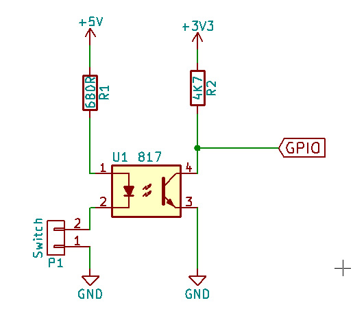
If you don't want to remove the existing LED you can do this:
Use a resistor (330 ... 680 Ohm) and connect it from the Out-pin 5/R736 / Collector of T704 connection point to the LED of the opto coupler pin1. Connect the pin 2 from the opto coupler to ground of the circuit.
The output side can be connected directly to the GPIO pin, a pullup resistor (4,7KOhm) is connected from the GPIO to 3,3V (NOT 5V!!!).
Shardan


