Page 1 of 1
ESP-12 Relay Board Strange Behavior
Posted: 09 Dec 2020, 20:11
by rmhoutz
Friends
I have a ESP Relay board from electrodragon.com
https://www.electrodragon.com/product/w ... d-esp8266/

I'm running firmware build 20111 - Mega
I'm attempting to add momentary switches to the available GPIO pins and turn the relay's on or off.
The problem I have is the GPIO pins don't act the same even if configured the same.
I don't know if this is a software problem or hardware problem so I'm hoping you guys can help.
For example I setup a input switch with Internal PullUP on GPIO-15 and momentary switch across it and 3.3v
When I press the button I see the pin pulled high as seen in the log. SW : GPIO=15 State=1 Output value=1
But I can't get GPIO-4 or GPIO-5 to show any kind of state change.
Here is the schematic. As far as I can tell GPIO15 and GPIO4 or 5 should work the same as they are directly connected to the header pin.

Any help or advice is greatly appreciated.
Re: ESP-12 Relay Board Strange Behavior
Posted: 10 Dec 2020, 03:44
by rmhoutz
I just figured out the labeling on this relay board is not correct. The Pin labeled as GPIO5 is actually connected to the ESP on GPIO4. The header pin labeled as GPIO5 is actually connected to ESP GPIO4. In simpler terms they are labeled backwards.
I'm still confused as to what determines if the default pin mode is a input or output and if it's normally high or low.
Re: ESP-12 Relay Board Strange Behavior
Posted: 10 Dec 2020, 10:37
by TD-er
Some of those default states may be determined by pull-up resistors on the board which are needed to boot the ESP into the correct mode.
For example GPIO-0 and 2 MUST be pulled up at boot and GPIO-15 MUST be pulled down at boot.
See also this page and the links on it:
https://espeasy.readthedocs.io/en/lates ... on-esp8266
Whether a pin is input or output may be determined by the task/plugin using the pin.
You can also set a boot state on the Hardware tab in the web interface.
But those are set by ESPEasy, so it will be set after the ESP is booted and ESPEasy starts.
Those settings only can activate internal pull-up resistors (and on GPIO-16 a pull-down), which have a resistance of 50k - 100k, so they are quite weak.
Re: ESP-12 Relay Board Strange Behavior
Posted: 10 Dec 2020, 22:38
by rmhoutz
Thanks TD-er
That was a big part of my confusion the header pin GPIO15 I was trying to use would change it's state on boot.
I was avoiding using GPIO header 4 and 5 because the mislabeling was confusing me also. Now that I figured out it was simply a swap of the labeling everything is working as I expected it to.
Thanks again for your input.
Re: ESP-12 Relay Board Strange Behavior
Posted: 10 Dec 2020, 22:52
by TD-er
You're welcome.
Maybe you can post some image here with the correct GPIO pins, in case someone else ends up on this topic with the same problem.
Re: ESP-12 Relay Board Strange Behavior
Posted: 16 Apr 2021, 15:26
by rmhoutz
Hi TD-er
I'm trying to find a place on the web to host my image so it can be viewed here. Do you have a place I can do that?
Re: ESP-12 Relay Board Strange Behavior
Posted: 16 Apr 2021, 15:34
by Ath
rmhoutz wrote: ↑16 Apr 2021, 15:26
I'm trying to find a place on the web to host my image so it can be viewed here. Do you have a place I can do that?
You can attach images and other (.zip) files to each post, in the Attachments tab, below the area where you are typing your message.
Re: ESP-12 Relay Board Strange Behavior
Posted: 16 Apr 2021, 16:46
by rmhoutz
Attention anyone that purchased this device
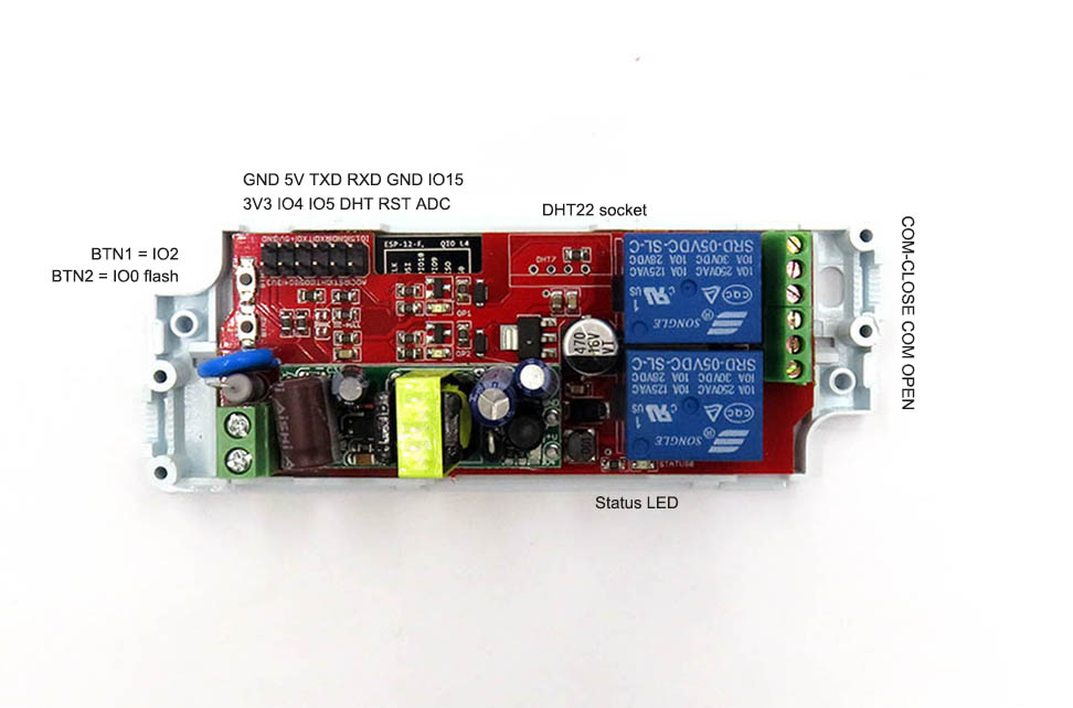
- ESP_Relay_Board_SPDT_01.jpg (86.53 KiB) Viewed 11381 times
from ElectroDragon should verify the connection of GPIO4 and GPIO5 (labeled as IO4 and IO5) using a continuity tester as the labeling on the board could be wrong.
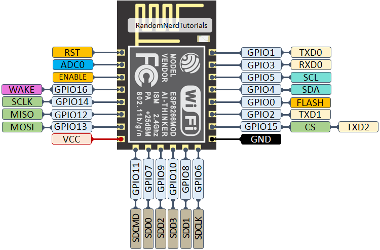
- ESP8266-ESP-12E-chip-pinout-gpio-pin.png (27.67 KiB) Viewed 11381 times