Difference between revisions of "ProMiniExtender"
| (8 intermediate revisions by 3 users not shown) | |||
| Line 3: | Line 3: | ||
Each individual pin can be used as either input or output. | Each individual pin can be used as either input or output. | ||
| + | |||
| + | = ProMini related Sofware = | ||
| + | The Arduino Pro Mini needs to be flashed with the appropriate software in order to interact with the ESPEasy device as intended. | ||
| + | You can find the related sketch here: https://codebender.cc/sketch:394847#prominiextender%20easyesp.ino | ||
| + | or here: | ||
| + | https://github.com/letscontrolit/ESPEasySlaves/tree/master/MiniProExtender | ||
| + | |||
= Hardware = | = Hardware = | ||
| Line 15: | Line 22: | ||
Direct connection possible when the Pro Mini runs on 3V3 VCC only! | Direct connection possible when the Pro Mini runs on 3V3 VCC only! | ||
| − | PME ESP | + | '''PME''' '''ESP''' |
GND GND | GND GND | ||
VCC VCC | VCC VCC | ||
| − | SDA GPIO | + | SDA SDA, GPIO 4 (standard setting) |
| − | SCL GPIO | + | SCL SCL, GPIO 5 (standard setting) |
| − | |||
| − | + | = ESP Easy = | |
Configuration depends on how you want to use a certain port on this device. Ports are numbered 0 to 13 when using a digital port. For analog (PWM) output pins, they are numbered from 0 to 7. | Configuration depends on how you want to use a certain port on this device. Ports are numbered 0 to 13 when using a digital port. For analog (PWM) output pins, they are numbered from 0 to 7. | ||
| − | + | == Input == | |
To have an input port act as an input switch device (just like with the default onboard GPIO pins) you need to edit a ESP Easy task and select the "ProMini Extender" device. | To have an input port act as an input switch device (just like with the default onboard GPIO pins) you need to edit a ESP Easy task and select the "ProMini Extender" device. | ||
| Line 34: | Line 40: | ||
You then select the portnumber and additional configuration depending on the controller type. For Domoticz, you enter the IDX that was allocated by Domoticz for this virtual switch. You have to select between using a digital or analog (PWM) port. | You then select the portnumber and additional configuration depending on the controller type. For Domoticz, you enter the IDX that was allocated by Domoticz for this virtual switch. You have to select between using a digital or analog (PWM) port. | ||
| − | === | + | == Output == |
| + | |||
| + | === Basic on/off === | ||
| + | We can control the pin with simple http url commands. To change the pin to high or low steady output: | ||
| − | + | '''<nowiki>http://<ESP IP address>/control?cmd=EXTGPIO,<pin>,0</nowiki>''' | |
| + | |||
| + | '''<nowiki>http://<ESP IP address>/control?cmd=EXTGPIO,<pin>,1</nowiki>''' | ||
| + | |||
| + | |||
| + | === PWM control === | ||
| + | To set a certain PWM level: | ||
| + | |||
| + | '''<nowiki>http://<ESP IP address>/control?cmd=EXTPWM,<pin>,<level></nowiki>''' | ||
| + | |||
| + | |||
| + | === Short pulses === | ||
| + | To send a pulse to a certain pin: | ||
| + | |||
| + | '''<nowiki>http://<ESP IP address>/control?cmd=EXTPulse,<pin>,<state>,<duration></nowiki>''' | ||
| + | |||
| + | Example to send an active high pulse on GPIO 2 for 500 milliseconds: | ||
| − | + | '''<nowiki>http://<ESP IP address>/control?cmd=EXTPulse,2,1,500</nowiki>''' | |
| − | |||
| − | + | = Optional settings = | |
| − | + | [[ EasyValueNames | Use of value names]] | |
Latest revision as of 13:44, 17 September 2017
Contents
Introduction
The number of GPIO pins on the ESP module can be expanded with a special IO Expander that's build upon a cheap Arduino Pro Mini board. From here we will call it the PME. We will use the PME that provides more pins that can be used as analog and digital input and output.
Each individual pin can be used as either input or output.
The Arduino Pro Mini needs to be flashed with the appropriate software in order to interact with the ESPEasy device as intended. You can find the related sketch here: https://codebender.cc/sketch:394847#prominiextender%20easyesp.ino or here: https://github.com/letscontrolit/ESPEasySlaves/tree/master/MiniProExtender
Hardware

The PME needs to be connected through the I2C interface. If you run the PME on 3V3, you can connect the I2C bus directly to the ESP module. (Most 5V Pro Mini boards seem to run fine on 3V3, although the official specs tell you that 16MHz will be out of spec on this lower voltage).
If you run the board on 5V, you would need I2C levelshifters to connect the I2C bus to the ESP module.
Connections
Direct connection possible when the Pro Mini runs on 3V3 VCC only!
 PME 		ESP
 GND 	 	GND
 VCC    	VCC
 SDA		SDA, GPIO 4 (standard setting)
 SCL		SCL, GPIO 5 (standard setting)
ESP Easy
Configuration depends on how you want to use a certain port on this device. Ports are numbered 0 to 13 when using a digital port. For analog (PWM) output pins, they are numbered from 0 to 7.
Input
To have an input port act as an input switch device (just like with the default onboard GPIO pins) you need to edit a ESP Easy task and select the "ProMini Extender" device.
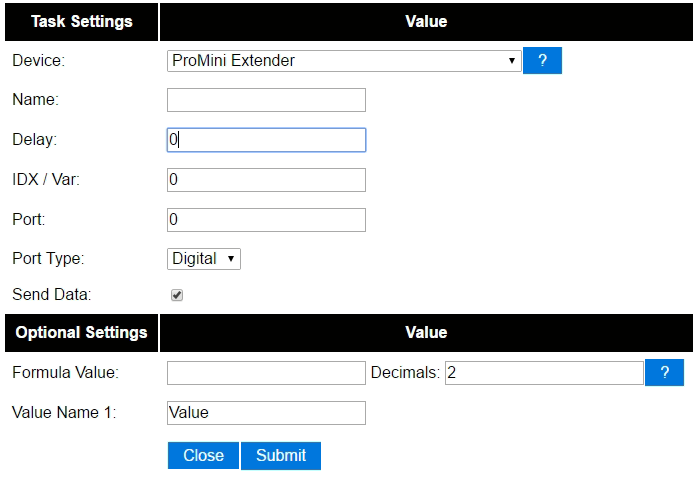

You then select the portnumber and additional configuration depending on the controller type. For Domoticz, you enter the IDX that was allocated by Domoticz for this virtual switch. You have to select between using a digital or analog (PWM) port.
Output
Basic on/off
We can control the pin with simple http url commands. To change the pin to high or low steady output:
http://<ESP IP address>/control?cmd=EXTGPIO,<pin>,0
http://<ESP IP address>/control?cmd=EXTGPIO,<pin>,1
PWM control
To set a certain PWM level:
http://<ESP IP address>/control?cmd=EXTPWM,<pin>,<level>
Short pulses
To send a pulse to a certain pin:
http://<ESP IP address>/control?cmd=EXTPulse,<pin>,<state>,<duration>
Example to send an active high pulse on GPIO 2 for 500 milliseconds:
http://<ESP IP address>/control?cmd=EXTPulse,2,1,500