NEXTIONDisplay
Contents
Introduction
This page is under contruction.
The OLED page is being used as a donor.
This is not an ordinary display. You cannot simply write data to it. You will first have to create an appropriate interface.
This is a very easy process when using the free Itead IDE (just search for Nextion on the web).
It has some good tutorials and once you have created your own display, it is very easy to present data and control devices with it.
The ESP8266 module can be used to control a serial Nextion display. Due to its on-board intelligence and the presence of a touch panel, the display can be used to control devices.
Hardware
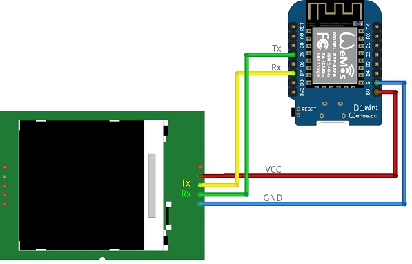
The board is connected to a controller by means of 4 wires.
Connect the Nextion display to a serial port and to +5 V and ground. The Nextion software module provides the use of a software serial port. So, it is not required to use the 'native'Tx and Rx ports of the controller. This display works with 5V and can be connected directly to the ESP module. The Tx pin of the Nextion is regulated to 3.3v making it safe to directly connect.
Connections
 LCD 	 	ESP
 GND 	 	GND
 VCC    	VCC
 Tx		GPIO port acting as Rx
 Rx		GPIO port acting as Tx
In order to get these displays to work properly you need to activate the pull-up of the Tx pin. A quick test is to set the pin to high (1) but for long turn you should enable the pull-up instead. If the pin is missing a pull-up you can add one yourself by soldering a 10k resistor from 3.3V to the pin.
Screen preparations
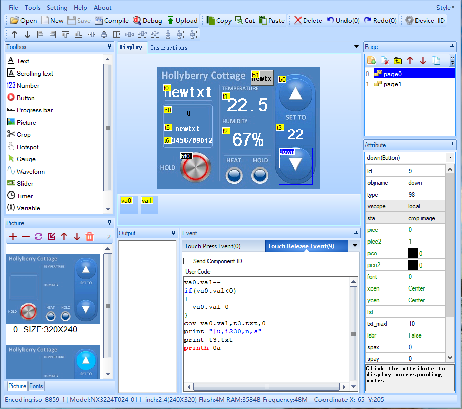
Although this is not the place to go into too much detail of the Nextion Editor, the examples help to explain the possibilities of the plugin. Please bear in mind, that this is the result of my experiments, no more, no less.
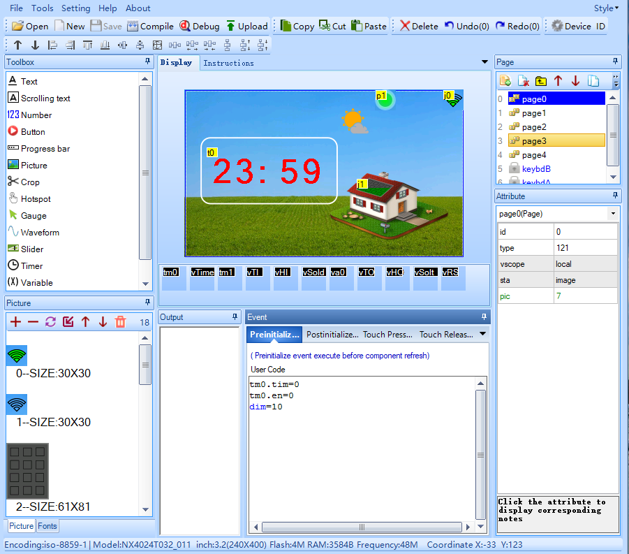
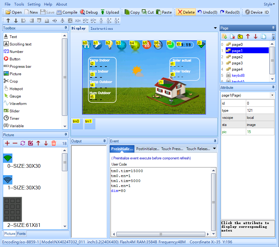
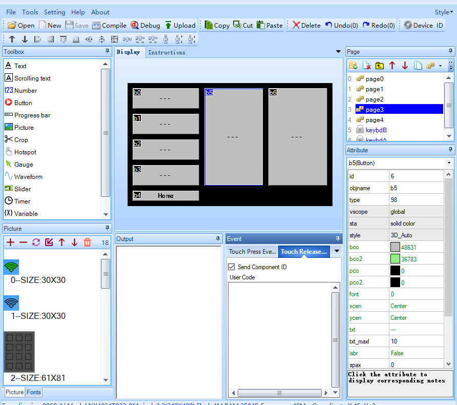
Let's assume you would like to have a control panel with several pages. Below is an example with 5 pages and some test pages. A front page, an info page and some switching pages. To make browsing between pages run smoothly without having to wait for databoxes to be filled, variables can be used. Several of them are declared and made global on the front page. The variables get their info from the ESPEasy in integer or text format. One timer, tm0, makes sure the control panel dims its backlight and go back to its start screen. Timer tm1 provides an update of the values once every 5000 msec.
Hereunder a step by step explanation.
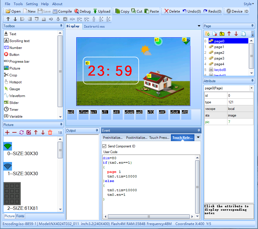
During pre initialisation, timer tm0 is set to 0 msec and disabled. The backlight is set to faint with dim=10. This is the standby mode
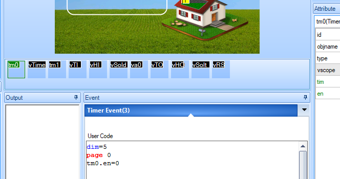
When timer tm0 fires, the backlight is set to very faint, the panel goes to page 0 (front page) and the timer is disabled. Again, this is the standby mode with an even lower brightness, to indicate the difference with start up.
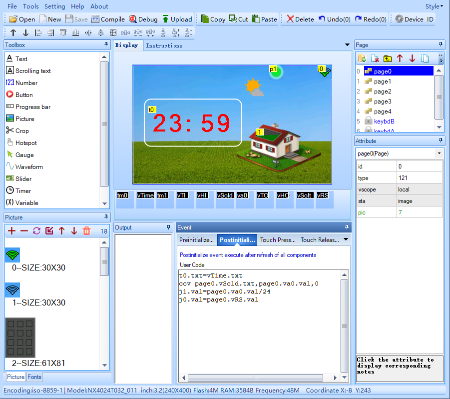
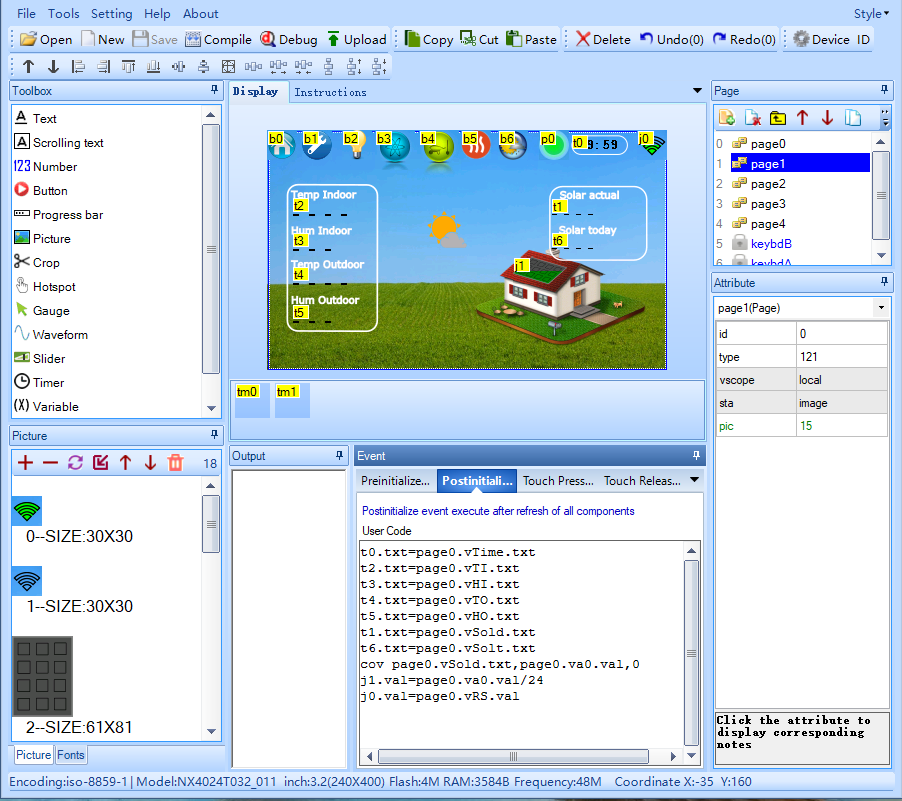
During the post initialisation of the page, after all boxes etc are made available, some data is written to various info boxes.
-clock time panel t0 gets the "actual" time from variable vTime.
-with command cov, the string containing solar energie value in vSold is converted to an int value in va0.
-solar indicator panel j1 gets the relative solar power value from variable va0.
-wifi indicator panel j0 gets the relative rssi power value from variable vRS.
Timer tm1 is programmed to provide periodic update (once every 5000 msec. when tm1 fires, data is written to various info boxes.
-clock time panel t0 gets the "actual" time from variable vTime.
-with command cov, the string containing solar energie value in vSold is converted to an int value in va0.
-solar indicator panel j1 gets the relative solar power value from variable va0.
-wifi indicator panel j0 gets the relative rssi power value from variable vRS.
Normally, the Nextion is in a standby mode. This means that a the Front page is active and the backlight is dimmed. ESPEasy sends updates to the Nextion, with stores them in the appropriate variables and boxes.
After the Nextion gets a tough release trigger, some actions are carried out:
-the backlight is set to 80% of the maximum brightness.
-if timer tm0 is already enabled, page 1 is selected the tm0 of that pages is charged.
this allows for a jump from the Front page, when it is touched for the second time within 10 seconds.
-if this is the first time Front page is touched, its own timer tm0 is charged and enabled.
ESP Easy
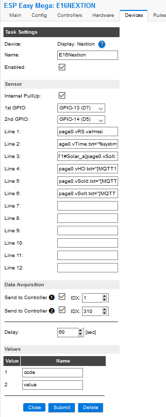
Use the device tab on the ESP Easy webinterface and create a new task by editing one of the available tasks. Select "Display - Nextion" from the dropdown box.
Now you first need to prepare your display. It needs to contain textboxes, numerical boxes etc. In the example below, I created variables vHO, vSold and vSolt. Data retrieved from a MQTT tasks can be written to it with:
page0.vHO.txt=[MQTT1#RFLWsTH_h]
where page0.vHO.txt describes the variable in the Nextion display, that I created beforehand.
Check this sample on how to get it done:
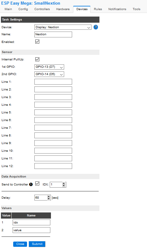
In the second example
The idx and value fields are used to communicate button presses etc.
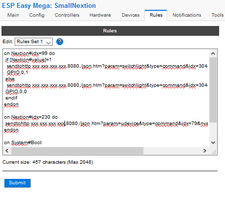
This info can be handled in the Rules:
(The upper (MQTT) IDX field will be stuffed with '1', because it's needs a value. But nothing will be send with this device the second one is to write to a debug text box in Domoticz, but could also be 1)
Commands
| Command | Value | Extra information |
|---|---|---|
| Nextion, | - | Write text messages to OLED screen, ROW for row, COL for starting column, and Text for text. |
| Nextion,<value> | Switch on or off the OLED or to clear the display. During the off state, the content will be updated according to the latest values or states. |
Special characters
Mass update [Domoticz, HTTP]
Introduction
This HowTo is intended for users who use Domoticz as their domotics platform and wish to synchronize the device settings in Domoticz with those in the Nextion display. This is especially convenient when the ESP/Nextion needs to obtain device settings from domoticz after reset.
Syncing can be initiated in the Rules section of the ESPEasy that interfaces to the display, for examply during boot up or with the flip of a switch.
Requirements
To make this work, we need to have:
- A Domoticz platform
- An ESPEasy with the latest firmware and Nextion display connected to it
- The devices to be updated in Nextion, must exist in Domoticz
- Some preparations to the attributes of devices in Domoticz
- A switch in Domoticz that directly triggers the update proces
- The update script written in dzVents
- Some basic understanding of the device attributes in Domoticz
This will all be explained in the following parts.
HowTo in steps
Common knowledge on how to use ESPEasy with Nextion in conjunction with Domoticz is assumed to be available.
If not, let us know and we will try to help.
dzVents and attributes
Domoticz preparations
Let us assume, for the sake of the example, that we have a Domoticz with:
- One wind sensor named RFLWsWind and
- Four switches, named RFLWsWind|RFLPontpump|RFLPontlight|RFLYardlight|RFLDoorlight
There are corresponding devices in the Nextion display and they relate as follows (note: the windsensor has three counterparts in Nextion):
| Domoticz device | Device attribute | Nextion device | data type | description |
|---|---|---|---|---|
| RFLWsWind | direction | page7.t0 | txt | page7.t0.txt= |
| RFLWsWind | direction | page4.z0 | val | page4.z0.val= |
| RFLWsWind | speed | page7.t1 | txt | page7.t1.txt= |
| RFLPontPump | nValue | page0.vFont | nValue | page0.vFont.val= |
| RFLPontLight | nValue | page0.vLight | val | page0.vLight.val= |
| RFLYardLight | nValue | page0.vErf | val | page0.vErf.val= |
| RFLDoorLight | nValue | page0.vAcht | val | page0.vAcht.val= |


